


1-5
Cisco Catalyst Blade Switch 3120 for HP Hardware Installation Guide
OL-12246-01
Chapter 1 Product Overview
Other Features
LEDs
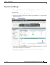
You can use the switch LEDs to monitor switch module activity and performance. Graphical
representations of the LEDs described in these sections are visible in the device manager.
• System LED, page 1-5
• Stack LED, page 1-5
• Stack Master LED, page 1-6
• Stack Member LED, page 1-6
• UID and Health LEDs, page 1-6
• RJ-45 Uplink Port LEDs, page 1-6
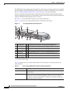
Note The System LED (SYST), stack LED (STCK), Stack Master LED (MSTR), and Stack Member LED
(MMBR) are shown as item 4 in Figure 1-1 on page 1-2.
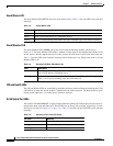
System LED
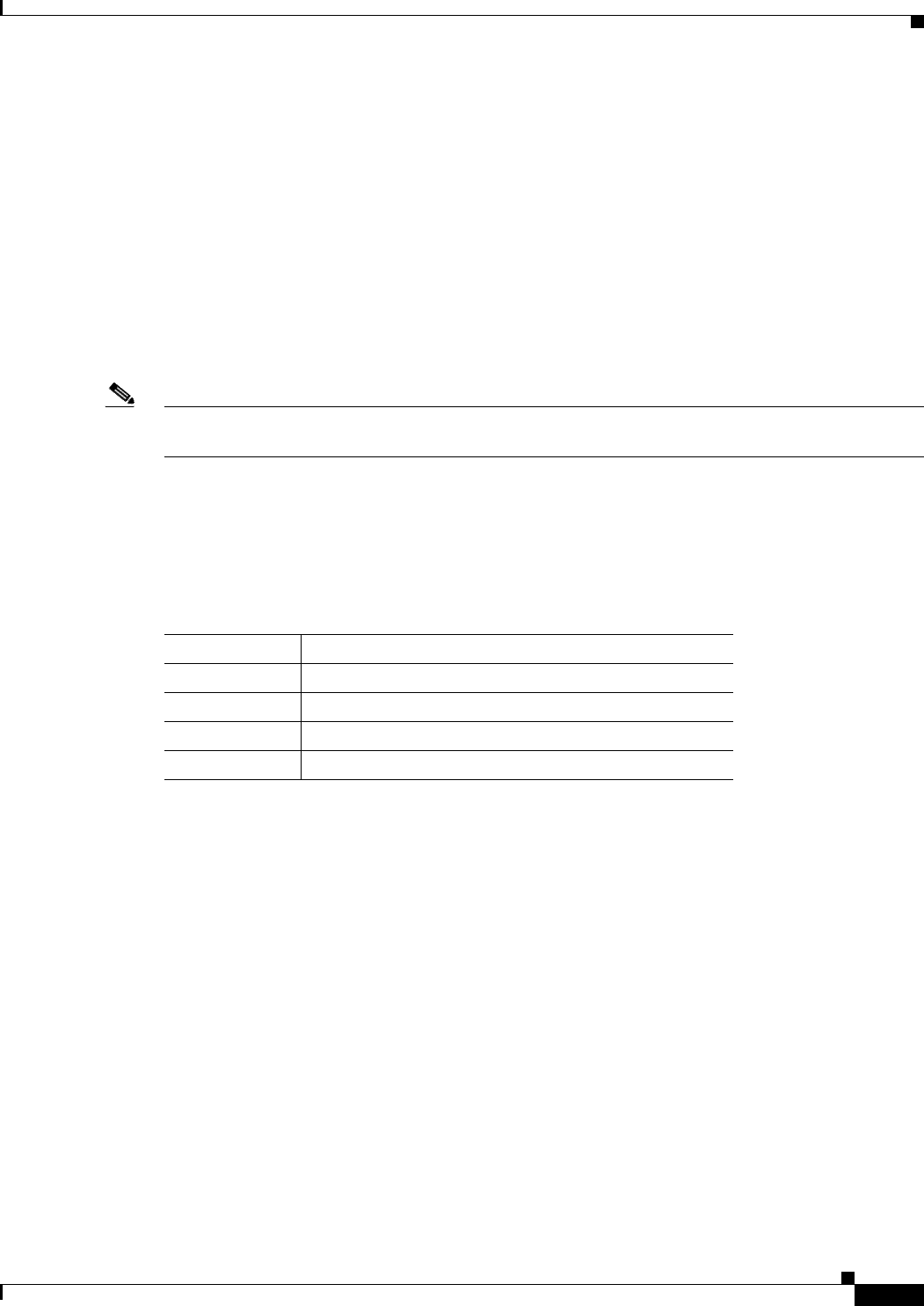
The System LED (SYST) shows whether the system is receiving power and is functioning properly.
Table 1-2 lists the LED colors and their meanings.
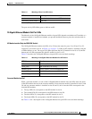
Stack LED
To see the status of the StackWise Plus ports, press the Mode button. The Stack LED (STCK) is green
when the StackWise Plus ports are up and amber when the ports are down. The bottom two 10-Gigabit
Ethernet module slot LEDs show the status for StackWise Plus ports 1 and 2, respectively (see item 11
in
Figure 1-1 on page 1-2).
When in stack mode, if both 10-Gigabit Ethernet uplink port LEDs are green, the stack is operating at
full bandwidth. If one or both of the 10-Gigabit uplink LEDs are not green, the stack is not operating at
full bandwidth.
See the “LED Behavior in Stack Mode” section on page 1-8 for more information.
Table 1-2 System LED
Color System Status
Off System is not powered on.
Blinking green POST is in progress.
Solid green System is operating normally.
Amber System is receiving power but is not functioning properly.