


2-3
Cisco Catalyst Blade Switch 3120 for HP Hardware Installation Guide
OL-12246-01
Chapter 2 Switch Installation
Preparing for Installation
Installation Guidelines
Before you install the switch module in the blade enclosure, read these guidelines:
• Review and become familiar with the safety and handling guidelines specified in the blade enclosure
Product Information Guide.
• Review the “Safety Warnings” section on page 2-2 and the Regulatory Compliance and Safety
Information for the Cisco Catalyst Blade Switch 3000 Series for HP that accompanies this guide.
Consider these prerequisites before installing your switch module:
• Fill any empty interconnect bays or any empty power module bays in the blade enclosure with
blanks.
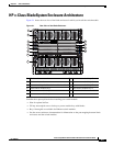
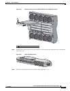
• Identify the bays in which you will insert the switch modules. Plan to install the first switch module
in bay 1, the second in bay 2, and so on up to bay 8, if possible. The bay in which you choose to
install each switch module depends on whether mezzanine or Ethernet cards are installed in the
blade enclosure and how they are configured. See the blade enclosure documentation for more
information about installing and configuring the mezzanine or Ethernet cards.
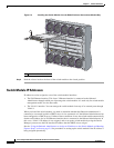
The interconnect module bays are physically interconnected in pairs through the blade enclosure
backplane. That is, each of these pairs—bays 1 and 2, bays 3 and 4, bays 5 and 6, and bays 7 and
8—are interconnected. If you install two switch modules in one of the paired bays, they are
internally interconnected. You must configure the switch modules to logically enable the
interconnect ports, Gigabit Ethernet ports 23 and 24. See the switch module software configuration
guide for information on configuring these ports.
• See the HP c-Class documentation for information on the port mapping between blade enclosures
and the switch modules.
Caution To prevent electrostatic-discharge (ESD) damage when installing switch modules, follow your normal
board and component handling procedures.
When you install a switch module, you do not need to power down the server modules or the enclosure.
The initial configuration assumes that the switch module was never configured, that it is in the same state
as when it was received, and that it is not configured with a default username and password.
Be sure to observe these requirements:
• For copper Ethernet ports, cable lengths from the switch module to connected devices can be up to
328 feet (100
meters).
• See the documentation for the SFP module for more information about cable specifications for the
SFP module connections. Also see the
“SFP Module Cable Specifications” section on page B-6.
Each port must match the wave-length specifications on the other end of the cable, and the cable
must not exceed the stipulated cable length for reliable communications.
Note When using shorter lengths of single-mode fiber-optic cable, you might need to insert an inline
optical attenuator in the link to avoid overloading the receiver.
• Operating environment is within the ranges listed in Appendix A, “Technical Specifications.”
• Cabling is away from sources of electrical noise, such as radios, power lines, and fluorescent
lighting fixtures. Make sure the cabling is safely away from other devices that might damage the
cables.