


3-2
Cisco Catalyst Blade Switch 3120 for HP Hardware Installation Guide
OL-12246-01
Chapter 3 Troubleshooting
Diagnosing Problems
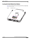
Look at the Switch Module LEDs
You must have physical access to the switch module to do this. Look at the port LEDs for troubleshooting
information about the switch module. See the
“LEDs” section on page 1-5 for a description of the LED
colors and their meanings.
Confirm the Switch Module Connections
Review this section when troubleshooting switch module connectivity problems.
Bad or Damaged Cable
Always test the cable for marginal damage or failure. A cable might be sufficient to connect at the
physical layer but then cause packet corruption because of subtle damage to its wiring or connectors.
You can identify this situation because the port will have many packet errors, or the port will constantly
lose and regain link. In these situations:
• Exchange the copper or fiber-optic cable with a known, good cable.
• Look for broken or missing pins on cable connectors.
• Rule out any insufficient patch panel connections or media convertors between the source and the
destination. If possible, bypass the patch panel or eliminate faulty media convertors, such as
fiber-optic-to-copper convertors.
• Try using the cable in another port or interface to see if the problem also exists there.
Ethernet and Fiber Cables
Make sure that you have the correct cable type for the connection:
• For Ethernet, use Category 3 copper cable for 10 Mb/s unshielded twisted pair (UTP) connections.
Use either Category 5, Category 5e, or Category 6 UTP for 10/100 or 10/100/1000 Mb/s
connections.
• For fiber-optic connectors, verify that you have the correct cable for the distance and port type.
Make
sure that the ports on the connected device match and that they use the same type of encoding,
optical frequency, and fiber type. For more information about cabling, see
Appendix B, “Connector
and Cable Specifications.”
• For copper connections, determine if a crossover cable was used when a straight-through cable was
required, or the reverse. Enable auto-MDIX on the switch module, or replace the cable.
Link Status
Verify that both sides have link. A single broken wire or one shutdown port can cause one side to show
link, but the other side does not have link.
A link LED does not guarantee that the cable is fully functional. The cable might have encountered
physical stress that causes it to function at a marginal level. If the link light for the port does not come on:
• Connect the cable from the switch module to a known, good device.
• Make sure that both ends of the cable are connected to the correct ports.
• Verify that both devices have power.