


2-20
Cisco Catalyst Blade Switch 3120 for HP Hardware Installation Guide
OL-12246-01
Chapter 2 Switch Installation
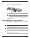
Installing Devices in the 10-Gigabit Ethernet Slots
Step 5 Reinstall the dust cover in the 10-Gigabit Ethernet slot.
Caution The dust covers should always remain in place unless a module is installed in the slot.
Step 6 Place the module in an antistatic bag or other protective environment.
Installing SFP Modules
This section describes how to install and remove SFP modules in the 10-Gigabit Ethernet slots. To use
SFP modules in the switch, you must have a converter module installed in a 10-Gigabit Ethernet slot.
Caution To avoid damage to the converter module, first install the converter module in the switch 10-Gigabit
Ethernet slot before installing the SFP modules.
See the switch module release notes on Cisco.com for the list of SFP modules that the switch module
supports. Use only Cisco SFP modules on the switch. Each Cisco module has an internal serial EEPROM
that is encoded with security information. This encoding provides a way for Cisco to identify and
validate that the SFP module meets the requirements for the switch.
For more information about installing, removing, cabling, and troubleshooting SFP modules, see the
module documentation that shipped with your device. For module cable specifications, see
Appendix B,
“Connector and Cable Specifications.”
Installing an SFP Module
To insert an SFP module into a converter module slot, follow these steps:
Step 1 Attach an ESD-preventive wrist strap to your wrist and to a bare metal surface.
Step 2 Remove the Cisco TwinGig Converter Module dust cover and save.
Note The dust cover is an integral part of the airflow function. If you remove the SFP module, you must
replace it with the saved dust cover.
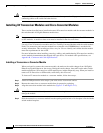
Step 3 Install the converter module in the 10-Gigabit Ethernet module slot as described in “Installing a
Transceiver or Converter Module” section on page 2-18.
Step 4 Find the send (TX) and receive (RX) markings that identify the top side of the SFP module.
On some SFP modules, the send and receive (TX and RX) markings might be replaced by arrows that
show the direction of the connection, either send or receive (TX or RX).
Step 5 If the SFP module has a bale-clasp latch, move it to the open, unlocked position.
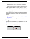
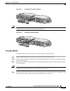
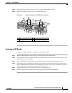
Step 6 Align the SFP module in the converter module opening. When installing a module in the upper module
slot (slot 1), position the SFP module face up. When using the lower module slot (slot 2), position the
SFP module face down.
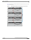
Step 7 Slide the SFP module into the opening until you feel the connector on the module snap into place
(
Figure 2-14).