


2-9
Cisco Catalyst Blade Switch 3120 for HP Hardware Installation Guide
OL-12246-01
Chapter 2 Switch Installation
Using the Onboard Administrator to Assign an IP Address to the Switch Module and Running Express Setup
Using the Onboard Administrator to Assign an IP Address to the
Switch Module and Running Express Setup
Before you run Express Setup, you must set up your switch module to communicate with a hyperterminal
program. The initial configuration assumes that the switch module was never configured, that it is in the
same state as when it was received, and that it is not configured with a default username and password.
To set up the switch module by using the command-line interface (CLI), see the switch module hardware
installation guide on Cisco.com.
For the switch module to obtain an IP address for the Fa0 interface through the Onboard Administrator,
these conditions must be met:
• The blade enclosure is powered on and connected to the network.
• Basic configuration of the Onboard Administrator is completed, and you have the username and
password for the Onboard Administrator.
• A DHCP server is configured on the network segment to which the blade enclosure is connected,
or
the Onboard Administrator is configured to run as a DHCP server.
See the Onboard Administrator user guide at http://www.hp.com/go/bladesystem/documentation for
more information about configuring and using the Onboard Administrator.
After you install the switch module in the interconnect module bay, after approximately 2 minutes, the
switch module automatically obtains an IP address for its Fa0 interface through the Onboard
Administrator. This method of obtaining an IP address occurs if a DCHP server is configured on the same
network, or if the Onboard Administrator is configured as a DHCP server.
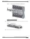
After you have installed the switch module (see the “Installing the Switch Module in the Blade
Enclosure” section on page 2-6), it powers on. The switch module begins the POST, a series of tests that
runs automatically to ensure that the switch module functions properly.
Step 1 Wait for the switch module to complete POST. It might take several minutes for the switch module to
complete
POST.
Step 2 Verify that POST has completed by confirming that the system and status LEDs remain green.
If the switch module fails POST, the system LED turns amber. If the POST fails, see the “Verify the
Switch Module POST Results” section on page 3-1 to determine a course of action. POST errors are
usually fatal. Call Cisco Systems immediately if your switch module fails POST.
Step 3 Wait approximately 2 minutes for the switch module to get the software image from its flash memory
and to begin autoinstallation.
If you already have the Onboard Administrator open through a browser window, go to Step 5.
Step 4 Using a PC that is connected to the same network segment as the blade enclosure Onboard
Administrator, access the Onboard Administrator in a browser window. Enter your assigned user name
and password.
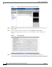
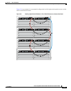
Step 5 Choose Enclosure Information > Interconnect Bays to open the Interconnect Bay Summary window
where you can find the assigned IP address of the switch module Fa0 interface in the Management URL
column. (See
Figure 2-5.)