


2-18
Cisco Catalyst Blade Switch 3120 for HP Hardware Installation Guide
OL-12246-01
Chapter 2 Switch Installation
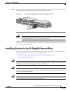
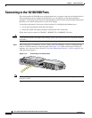
Installing Devices in the 10-Gigabit Ethernet Slots
Caution To prevent ESD damage, follow your normal board and component handling procedures when
connecting cables to the switch and other devices.
Installing X2 Transceiver Modules and Cisco Converter Modules
These sections describe how to install and remove X2 transceiver modules and the converter modules in
the switch module 10-Gigabit Ethernet module slots.
Note Do not remove the dust cover from the converter module until you are ready to install an X2 transceiver
or SFP modules. A module or dust cover must be installed in the slot at all times.
Use only Cisco X2 transceiver modules and Cisco TwinGig Converter Modules with the switch module.
Each Cisco transceiver and converter module has an internal serial EEPROM that is encoded with
security information. This encoding provides a way for Cisco to identify and validate that the module
meets the requirements for the switch.
For more information about installing, removing, cabling, and troubleshooting X2 transceiver modules,
see the module documentation that shipped with your device. For module cable specifications, see
Appendix B, “Connector and Cable Specifications.”
Installing a Transceiver or Converter Module
When you install or remove the converter module, the mode on the switch changes from 10-Gigabit
Ethernet to Gigabit Ethernet or the reverse. During this mode change, data traffic on the other switch
module uplink ports (X2 transceiver or SFP module ports) might temporarily stop. When you install or
remove an X2 transceiver or SFP module, traffic delay does not occur.
To insert an X2 transceiver module or a converter module, follow these steps:
Step 1 Attach an ESD-preventive wrist strap to your wrist and to a bare metal surface.
Step 2 Remove the transceiver or converter module from its protective packaging.
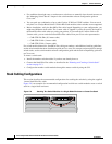
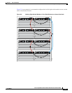
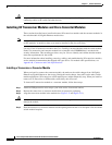
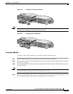
Step 3 Align the transceiver module in the module slot (Figure 2-12 and Figure 2-13).
Caution Verify the correct orientation of your module before inserting it into the slot. Incorrect insertion can
damage the module.
Step 4 Slide the transceiver or converter module into the opening until the back of its faceplate is flush with the
switch module faceplate.