


B-1
Cisco Catalyst Blade Switch 3120 for HP Hardware Installation Guide
OL-12246-01
APPENDIX
B
Connector and Cable Specifications
This appendix describes the cables and adapters that you use to connect that you use to connect the
switch module to other devices. This appendix includes these sections:
• Connector Specifications, page B-1
• Cable and Adapter Specifications, page B-4
Connector Specifications
These sections describe the connectors used with the switch:
• 10/100/1000 Ports, page B-1
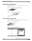
• 10-Gigabit Ethernet Module Interfaces, page B-3
• Cisco TwinGig Converter Module Ports, page B-3
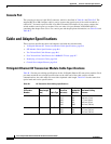
• Console Port, page B-4
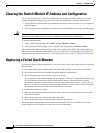
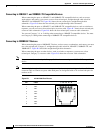
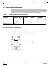
10/100/1000 Ports
The 10/100/1000 Ethernet ports on the switch module use standard RJ-45 connectors. Figure B-1 shows
the pinout.
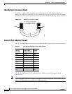
Note You can use the mdix auto interface configuration command in the CLI to enable the automatic
medium-dependent interface crossover (auto-MDIX) feature. When the auto-MDIX feature is enabled,
the switch module detects the required cable type for copper Ethernet connections and configures the
interfaces accordingly. Therefore, you can use either a crossover or a straight-through cable for
connections to a copper 10/100/1000 or 1000BASE-T SFP module port on the switch module, regardless
of the type of device on the other end of the connection.
For configuration information for this feature, refer to the switch module software configuration guide
or the switch module command reference.