


86
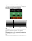
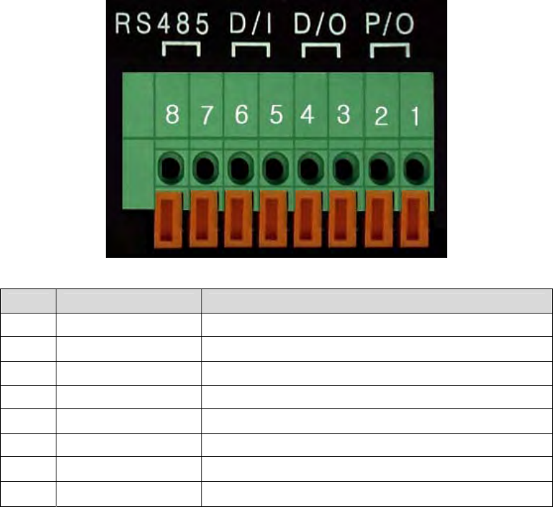
Appendix F: The I/O Connector (MPEG4 Cameras)
The I/O Connector provides the physical interface to a digital output and a single digital, photo-
coupled input that is used for connecting a variety of external alarm devices to the Pro Series
Network Camera, including infrared sensors, switches and alarm relays.
In combination with the configurable alarm facilities, you can quickly develop a variety of
security applications that are triggered on time- or alarm-based events.
No. Function Description
1 Power GND (-) Power for the external I/O devices (-)
2 Power DC12V (+) Power for the external I/O devices (+)
3 Digital Out (+) Output for the external output devices (+)
4 Digital Out GND (-) Output for the external output devices (-)
5 Digital In (+) Input to the external Input devices (+)
6 Digital In GND (-) Input to the external input devices (-)
7 RS-485 (+) Not in use
8 RS-485 (-) Not in use
1-2 PIN
To supply external devices with power. PIN 1 is connected to the GND terminal of a device’s
power and PIN 2 is connected to the positive (+) terminal. However, the external device should
be less than 12 V DC and 200 mA. This is a permanent 12 V DC power source.
3-4 PIN
To supply external devices with power. PIN 4 is connected to the GND terminal of a device’s
power and PIN 3 is connected to the positive (+) terminal. However, the external device should
be less than 12 V DC and 200 mA. Power is only provided if an alert state has occurred in the
Event Trigger Configuration (see section 6.5).
5-6 PIN
PIN 5 and PIN 6 are connected to the signal output terminal of an external input device, such as
an IR or alarm sensor.