


EN Camera Series
36 Connectors and Cables
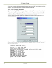
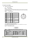
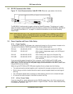
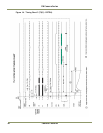
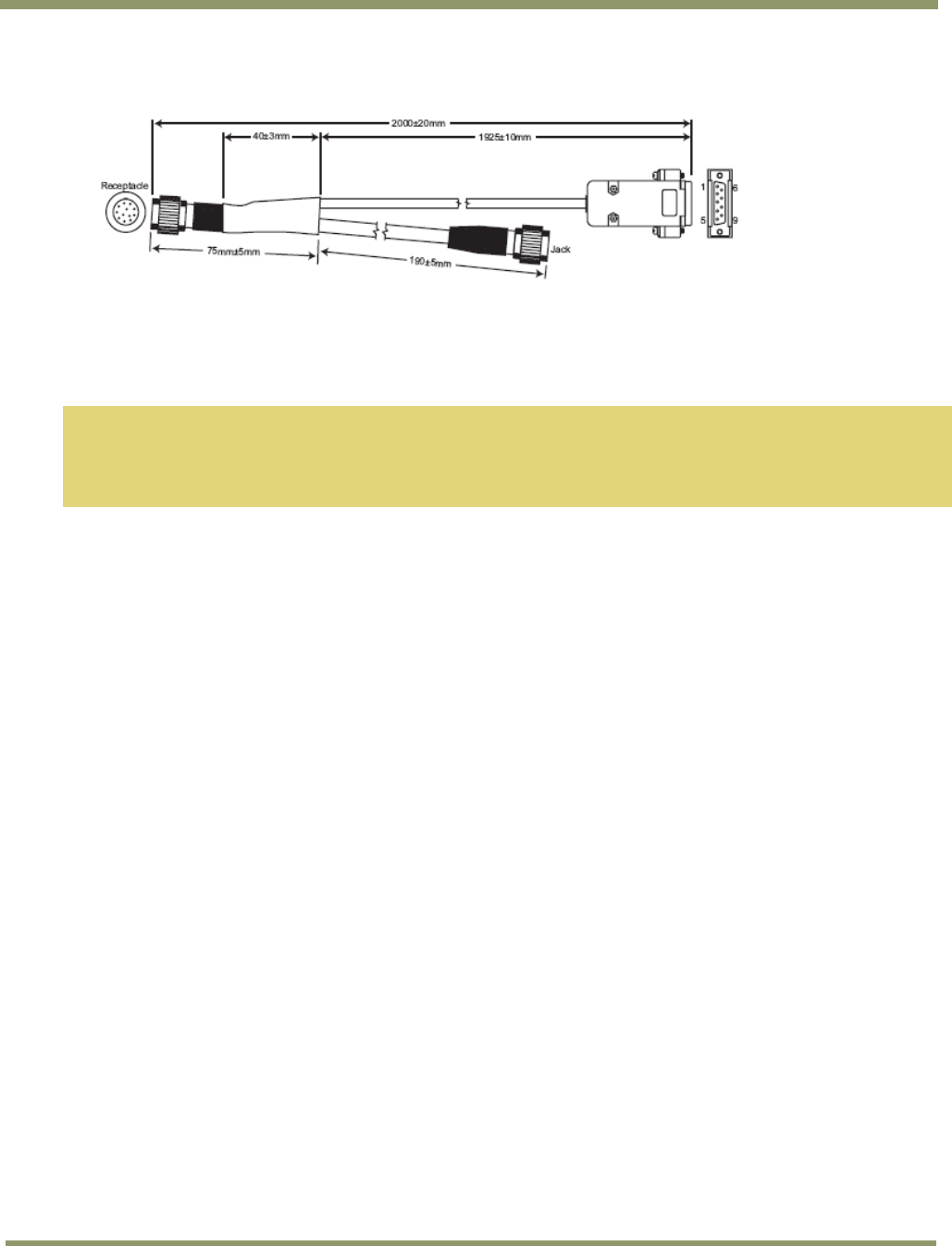
5.2 RS-232 Communication Cable
Figure 13. Serial Communications Cable RS-232B-12 (JAI Inc. part number: 310 132 19)
The RS-232B-12 interface cable is used to debug the PowerPC processor. This debug port is useful
when the network is down and RS-232 is the only choice to connect with the EN camera. See Section
3.6.3 on page 24 and Section 4.7 on page 31 for detailed information on how to use the debug
PowerPC port.
Note: Please make sure not to “hot” plug this cable into the camera (i.e. Plugging in while camera is
on), unless your laptop or desktop PC is properly grounded. A PC with a floating ground can
damage the internal circuit of the EN camera or your PC’s serial port as soon as the debug
(RS-232B-12) cable is connected.
5.3 Power Supplies and Power Cable Setup
5.3.1 Power Supplies
The EN Camera requires 12V DC power that is obtained through the 12-pin connector located on the
rear panel of the camera. PULNiX recommends the following power supplies:
PD-12UU 100-240V AC/12V DC 1.2A universal voltage power supply with US Plug
PD-12UUP 100-240 V AC 1.2A universal voltage power supply, with US Plug and
12-pin connector
PD-12UE 100-240V AC/12V DC 1.2A universal power supply with European Plug
PD-12UEP 100-240V AC/12V DC 1.2A universal power supply with European Plug and
12-pin connector
If you are providing power through the 12-pin connector, the PD-12UUP and PD-12UEP power
supplies are available with the 12-pin mating connector already attached to the leads from the
power supply. The PD-12UU and PD-12UE power supply can be connected to the JAI Inc. power cable
using a terminal strip or directly.
When wiring the PD-12UU and PD-12UE power supplies directly, please note the following:
• The lead ends must be twisted together and tin-soldered for strength and electrical continuity.
• Shrink tubing or a similar insulator should be used to prevent exposed leads from touching and
shorting.
• The +12V lead is marked with a red stripe or white lettering; be sure not to reverse the leads.
• All connections must be properly insulated to prevent shorting.
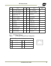
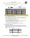
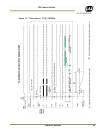
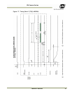
5.3.2 JAI Inc. Power Cables
If you are using JAI Inc. power cables such as the 12P-02S, please refer to the 12-pin connector pin-
out diagram. The cable pin-out diagram is shown in Figure 14 below. The color-coded leads use Gray
for Ground and Yellow for +12V.