


Connectors and Cables 37
EN Camera
Series
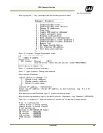
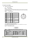
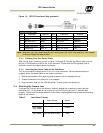
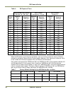
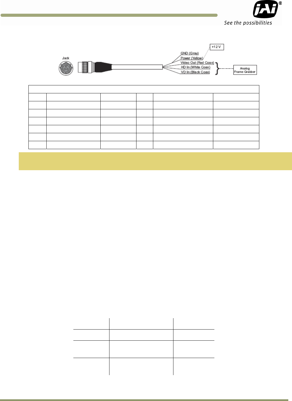
Figure 14. 12P-02S Interface Cable (optional)
12P-02S Interface Cable
Pin# Lead Color Function Pin#
Lead Color Function
1 Gray GND 7 Black coax Reserved
2 Yellow +12V DC 8 White coax shield Reserved
3 Red coax shield AGND 9 White coax Reserved
4 Red coax Video Out 10 Brown RxD
5 Orange coax shield GND 11 Blue Reserved
6 Orange coax VINIT IN 12 Black coax shield TXD
Note: Make sure that the unused leads are not touching and that there is no possibility that exposed
wires could cause the leads to short.
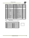
5.3.3 Building Your Own Power Cable
Refer to the 12-pin connector pin-out in Figure 14 on page 35. Connect the Ground lead to pin #1,
and the +12V DC lead to pin #2 of the 12-pin connector. Power must be DC-regulated, and of
sufficient current to properly power the camera.
5.3.4 Attaching the Power Cable to the Connector
The 12-pin connector is keyed and will only fit in one orientation. Follow these directions to
properly attach the power cable to the camera connector:
1. Rotate the connector while applying slight pressure until the keyways line up.
2. Press the connector into place until firmly seated.
3. Plug the power cord into the 100V AC socket. This will power the camera up.
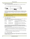
5.4 Attaching the Camera Lens
To attach the C-mount lens to the camera, carefully engage the threads and rotate the lens
clockwise until it firmly seats on the mounting ring. Do not force the lens if it does not seat
properly. Please note that some lenses with extremely long flangebacks may exceed the mounting
depth of the camera.
Table 5 Lens Mount Format
Sensor Format
Mount
TS(C)-1327EN
2/3”
C-Mount
TS(C)-2030EN
TS(C)-2076EN
1” C-Mount
TS(C)-4032EN
43.3mm
(Full size 35mm format)
M42