


EN Camera Series
48 Camera Features
on the output from the light sensor. The user can manually turn on and off the strobe and night light
if necessary. You need to be able to access the following registers by means of the EN setup
software.
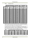
Register Address 10: Night Light Control
Register Address 11: Night Light ON threshold and Flash enable. Register Address 12: Night Light OFF
threshold and Flash enable. Register Address 50: Camera ADR Control
The distance and angle of the strobe unit toward the target is critical and must be optimized.
Please refer to the VIS400 Installation Manual for more information.
6.5 External Control
6.5.1 RS-485
The EN Camera has the ability to connect multiple cameras on the same RS-485 network. Each
camera has an individual ID number selectable via control registers; Camera RS-485 group register
(address=107) and Camera RS-485 address registers (address=109). Thus it is possible to send a serial
RS-485 trigger to any or all of the cameras. RS-485 communication is accessed via the 26-pin
connector on the rear panel of the camera.
RS-485 is typically used by the lane controller to send serial trigger or to send DatalD message to
validate the HW TTL trigger.
RS-485 is a differential signal communication for longer distance. Since RS-485 is not a common port
for PCs, a plug-in 485 board such as ULTRA-485 (Industrial Computer Source, San Diego, CA, 800-
523-2320) or compatible is required.
6.5.2 Ethernet
The primary benefit of Ethernet is the scalability of the system; you can add as many EN cameras as
you want to the system. For example, you can connect up to 255 Ethernet devices to one class A
subnet. Command/Status register access and image transfer are securely done over TCP/IP protocol.
In addition to the message-based TCP image transfer, sniffing image on UDP is also supported.
Captured images are buffered inside EN camera, and can be automatically transferred to FTP
server. Ethernet trigger can be used for applications where time critical response is not required as
hardware TTL trigger.
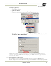
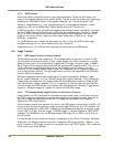
All functions over Ethernet are accessible by EN setup software. Please refer to VIS300/400EN Setup
User's Guide (Doc Number 4087-72-005).
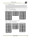
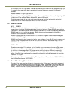
6.6 Color Filter Array (Color Version)
The color filter array requires software to interpolate color. If the proper interpolation software is
not present the camera provides an 8-bit monochrome image. The necessary DLL is available from
JAI Inc.. The JAI Inc. EN Camera cameras use the Bayer color mosaic filter pattern (see Figure 16
below). The CFA contains 50% green photo sites and 25% red and 25% blue photo sites.