


Introduction
13
Introduction
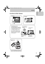
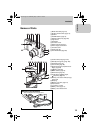
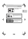
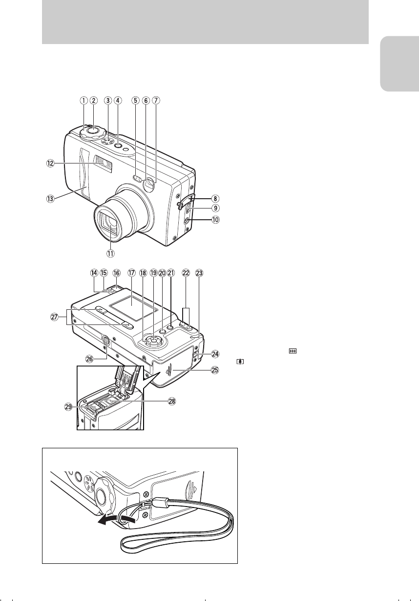
Names of Parts
1Mode select dial (page 16)
2Shutter release button (page 19)
3Speaker
4POWER button (page 16)
5Self-timer LED (red) (page 99)
6Light sensor
7Viewfinder
8Connector cover
9USB connector (page 31)
0Power supply input socket
ALens/lens cover
BFlash (page 45)
CFront illumination(page 99)
DCaution LED (red) (page 100)
EStandby LED (green) (page 100)
FViewfinder (page 43)
GLCD monitor (page 96)
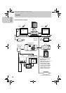
HDirectional keypad (Up/Down/Left/
Right) (page 26)
Ie button (page 26)
JMENU button (page 25)
KDISP. button (page 44)
LZoom buttons ( wide-angle,
telephoto) (page 42)
MMemory card access LED (orange)
(page 100)
NStrap lug
OMemory card door (page 14)
PTripod socket
Q(+) button/(–) button
RBattery cover (page 14)
SBattery cover release lever
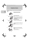
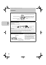
■ Attaching the Hand Strap
Attach the supplied hand strap as shown.
00_8CQ.book Page 13 Wednesday, May 14, 2003 8:10 PM