


– 101 –
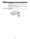
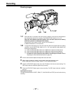
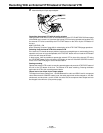
Connection With an External VTR
The unit is equipped with an interface which enables recording to be performed by an external
VTR.
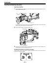
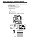
ÁMounting the AJ-YA900P 26-pin/12-pin output adaptor (option) and connecting the 26-pin cable
(option) to the unit allows recording to be performed by the VTR section (internal VTR) of the unit
and an external VTR. The component video signal is output from the 26-pin interface.
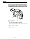
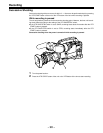
Precautions When Connecting an External VTR
ÁSet 26P CONTROL on the “VTR FUNCTION” setting menu to “BOTH” or “ON”.
(The factory setting is “OFF”.)
ÁSet SW201 on the CAM ENC board to ON. (Before the unit was shipped from the factory, this
switch was set to OFF.)
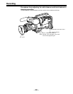
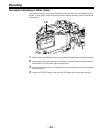
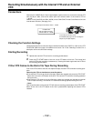
Power supply
Power is not supplied or received between the unit and the external VTR, so special power sup-
plies should be provided for each unit. The BATT lamp and remaining battery level display func-
tion inside the viewfinder indicate the power supply status only for the internal VTR. The power
supply status for the external VTR should be checked at the external VTR.
TALLY lamp and REC lamp operation
The unit’s TALLY lamp and the REC lamp inside the viewfinder indicate the REC status of the unit
when 26P CONTROL is set to BOTH. When 26P CONTROL is set to ON, these lamps indicate
the REC status of the external VTR.
Warning tone
External VTR-related warning tones are not output from the unit’s speaker or PHONES jack.
Note on connecting cables
The signals may not be connected properly with some cables.
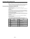
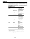
The signal assignments for the 26-pin/12-pin output adaptor AJ-YA900P (optional) are shown in
the following table. Use this table as a reference for connection with an external VTR.
Pin
No.
Signal
Pin
No.
Signal
1
2
3
4
5
6
7
8
Composite video signal
Composite video GND
Y GND
Y signal
PR signal
PR GND
PB signal
PB GND
9
10
11
12
15
18
19
B
CAM MIC (H)
CAM MIC (C)
CAM MIC (GND)
VTR START/STOP
REC TALLY
RET VIDEO
RET VIDEO GND
GND