


–59–
-40 -30 -25 -20 -15 -10 -5 0
E
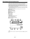
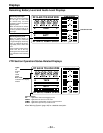
Status Displays Inside the Viewfinder Screen
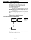
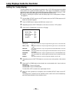
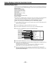
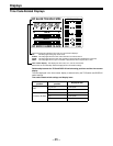
8 Audio level display
This displays the audio CH1 level.
During sine wave input, the audio level display corresponds roughly to the VTR level meter
display as follows.
9 Iris value display
This displays the approximate iris setting (F number).
10 Warning display
This displays the black balance, white balance, auto knee function, super iris, super gain
and other warning displays.
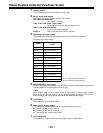
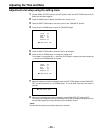
11 Safety zone marker
This indicates the safety zone to be the 80% or 90% (factory setting) range of the viewfinder
screen area.
The ratio of this area to the total screen area is selected on the VF DISPLAY page of the
setting menu.
ÁRefer to “Setting the Marker Displays” (page 62) for further details.
12 Center marker
This indicates the center of the viewfinder screen.
The marker appears when its display is set to ON on the VF DISPLAY page of the setting
menu.
13 Super iris ON display
This indicates that the super iris is ON.
14 MARK1/MARK2/TAKE display
If the MARK switch is pressed while the Picture Link function is used, M1 or M2 appears to
indicate the significance of the information concerned.
Nothing will appear if this function is not required.
Alternatively, T_ (TAKE) appears when the RET switch of the lens is used as the TAKE
function.
15 TCG display
This displays the time code generator value.
16 Master gain & super gain setting display
When the MODE CHECK button is pressed, the current GAIN L/M/H and SUPER GAIN
settings are displayed.
17 Battery setting display
This indicates the type of the battery currently being used.
1) Iris value display
The iris value is displayed when using a lens with the iris value display function.
Audio Channel 1 Level Display
VTR Level Meter