


– 154 –
Inspections Before Shooting
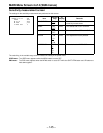
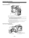
Inspecting the Viewfinder
1 Adjust the position of the viewfinder.
2 Check that the color bar appears on the viewfinder screen, and then adjust the BRIGHT,
CONTRAST and PEAKING controls so that the color bar appears clearly on the viewfinder.
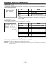
3 Check the following items.
(1) Press the PAGE button, and check that the setting MAIN menu appears on the viewfind-
er screen.
(2) Press the PAGE button, and check that the setting MAIN menu page changes.
(3) Press the SHIFT/ITEM button, and check that the cursor moves on the page.
(4) Press the UP or DOWN button, and check that one of the SUB menus opens.
(5) Press the SHIFT/ITEM button, and check that the cursor moves on the page.
(6) Press the UP or DOWN button, and check that the setting or ON/OFF display of the item
selected by the cursor changes.
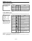
4 Set the OUTPUT/AUTO KNEE switch to CAM, and change the CC and ND filter knob set-
tings. Check that the number of the FILTER display on the viewfinder screen changes in
accordance with the knob position.
5 Perform the following operation and check that the (!) lamp lights when the items set to ON on
the “(!) LED” SUB menu page of MAIN menu screen 2 of 4 are operated.
(1) Set the gain to any value other than 0 dB with the GAIN switch.
(2) Set the SHUTTER switch to ON.
(3) Set the WHITE BAL switch to PRST.
(4) Insert the lens extender.
(5) Set the FILTER knob to any position other than “1”.
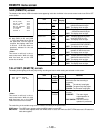
6 Press the SHUTTER switch repeatedly from the ON position to the SEL side and check that
the shutter setting on the viewfinder screen changes.
7 Aim the lens at an appropriate subject and turn the focus ring to bring the subject into focus.
Check the image appearing in the viewfinder.
8 Set both the AUDIO IN CH1 and CH2 switches to “FRONT MIC”, and set LEVEL METER on
the “VF INDICATOR” SUB menu page of the MAIN menu screen 2 of 4 to “CH1”.
Check that the audio level appears on the viewfinder screen when sound is input from the
microphone which has been connected to the MIC IN jack on the front panel.
Check that the audio level display is cleared from the viewfinder screen when LEVEL METER
on the “VF INDICATOR” SUB menu page of the MAIN menu screen 2 of 4 is set to “OFF”.
9 Check that the zebra pattern appears on the viewfinder screen when the ZEBRA switch is set
to ON, and disappears when the ZEBRA switch is set to OFF.
|Note{
Depending on the setting conditions, the items and functions in steps 3 to 6 may not operate.
If this is the case, switch the unit to the engineer mode, set DISPLAY MODE on the “VF DISPLAY”
menu page to “3”, and set the required items on the SHUTTER SPEED, (!) LED and USER MENU
SELECT pages 1 of 3 to 3 of 3.