


– 126 –
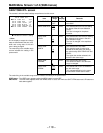
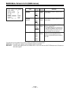
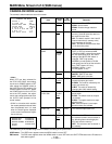
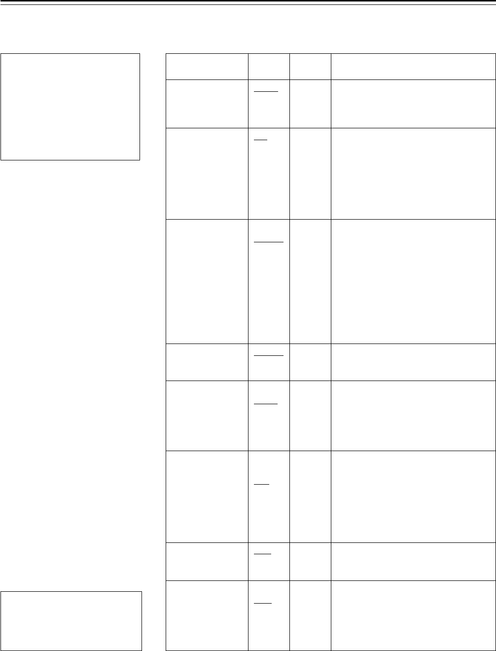
Item
SUPER V
FILTER INH
SHOCKLESS
AWB
COLOR BAR
S.GAIN OFF
S.IRIS/
S.BLK SW
S.BLK LVL
ECU DATA SAVE
Variable
range
FRM1
FRM2
ON
OFF
OFF
NORMAL
SLOW
FAST
SMPTE
SNG
S.GAIN
L/M/H
S.IRIS
S.BLK
INH
p10
p20
p30
ON
OFF
Remarks
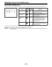
This selects ON or OFF for SUPER V.
FRM1: Normal mode
FRM2: Residual image reduction
mode
This switches whether the AWB
memory (A and B channels) data is to
be stored for each filter.
ON: The data is stored in the A and B
channel memories (2 memory units)
only regardless of the filter.
OFF: The data is stored for each filter.
(4q2r8 memory units)
This selects ON (NORMAL/SLOW/
FAST) or OFF for shockless AWB.
“Shockless AWB” ensures that a shock
will not result when the A, B or PRST
setting of the WHITE BAL switch is
changed. FAST (high speed),
NORMAL (normal speed) or SLOW
(low speed) can be set as the selection
time. FAST (approx. 0.5 sec),
NORMAL (approx. 1 sec),
SLOW (approx. 3 sec)
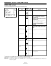
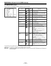
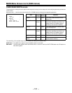
This selects the type of color bars.
SMPTE: SMPTE color bars
SNG: SNG (split) color bars
This selects the method used to
release the super gain mode.
S.GAIN: The mode is released by the
super gain switch only.
L/M/H: The mode is released by
changing the L/M/H switch setting.
This allocates the function of the side
panel switch.
S.IRIS: The switch works as a super
iris function.
S.BLK: The switch works as a super
black function.F
1
INH: Both the super iris and super
black functions are inhibited.
This sets the super black level.
ON: When the ECU is detached from
the camera recorder, the set values of
the following items controlled by the
ECU are stored in memory.F
2
OFF: The set values are not stored in
the memory.
VF
display
ENG
ENG
ENG
ENG
ENG
ENG
ENG
ENG
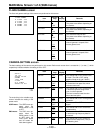
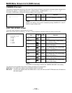
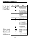
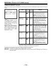
MAIN Menu Screen 2 of 4 (SUB menus)
CAMERA SW MODE screen
The camera’s switch modes are set on this screen.
CAMERA S
W
MODE
{
SUPER V
:
:
:
:
:
:
FRM1
FILTER INH
INH
SHOCKLESS A
W
B NORMAL
COLOR BAR SMPTE
S.
S.
GA I N OFF
IRIS S./BLK
W
S
L/M/H
ON
:
:
S. VLLBLK
ECU DATA SAVE OFF
¢
|
∂ 10
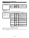
|Note{
When OFF has been selected for
the ECU DATA SAVE item setting,
set the unit’s POWER switch to OFF
after setting the POWER switch on
the AJ-EC3 to the OFF position. If its
POWER switch is set to OFF before
the POWER switch on the AJ-EC3 is
set to the OFF position, the adjust-
ments and settings performed when
the AJ-EC3 was operated will be
saved instead.
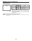
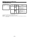
F
1
S.BLK is a function which enables
the master pedestal to be set lower
than the pedestal level. It is used
when the black figures displayed
on the screen have become lighter
due to mist, etc.
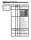
The underlining in the variable range column indicates the setting in the preset mode.
USER menu: The USER menu appears when the MENU switch is set to SET.
ENG menu: The ENG menu appears when the MENU switch is set to SET while the SHIFT/ITEM button and UP button are
held down together.
F
2
MASTER PED R PEDESTAL
MASTER DTL G PEDESTAL
MASTER GAMMA B PEDESTAL
R GAIN SYNCHRO SCAN
B GAIN