


21
Parts and their Functions: Shooting and Recording/Playback Functions Section
Parts and their Functions
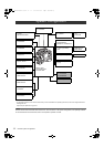
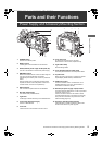
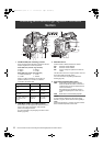
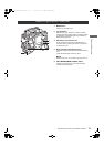
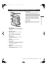
20. REW (rewind) button and lamp
During pause, this button performs a fast-reverse
playback with the lamp lights on.
During playback, it performs an approximately 4 fast-
reverse playback with the PLAY and REW lamps lights
on.
If this button is pressed when playback is paused, the
start of the clip being played back is located in pause
mode.
21. STOP button
This button stops playback.
22. FF (fast forward) button and lamp
During pause, this button is used to perform fast
playback with the lamp lights on.
During playback, it performs an approximately 4 fast
playback with the PLAY and FF lamps lights on.
If this button is pressed when playback is paused, the
start of the next clip is located in pause mode.
23. PLAY/PAUSE button
This button is used to view playback using the
viewfinder screen or a color video monitor. The lamp
comes on when playback starts.
In playback mode, this button pauses (PLAY/PAUSE)
playback with the lamp blinking.
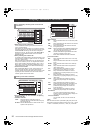
24. P2 card access LED
This LED indicates the recording and playback status of
each card.
25. Slide lock button
Used to open the slide-out door for inserting P2 cards.
While depressing this button, slide the door to the left.
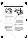
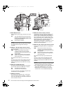
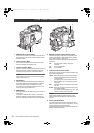
26. USB 2.0 connector (DEVICE)
27. USB 2.0 connector (HOST)
A USB 2.0 cable is connected here.
When the menu option PC MODE is set to “ON”, data
can be transferred via USB 2.0. During such data
transfer, recording, playback or operations of clips is
limited.
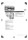
The menu option PC MODE is found in the <SYSTEM
MODE> screen on the SYSTEM SETTING page. For
more information, see [Connection with external devices
using the USB 2.0 port] (page 142).
28. GENLOCK IN connector
Used to input an HD Y signal when GENLOCKing the
camera or externally locking the time code. Alternatively,
a composite signal can be input as the reference signal.
Note that the subcarriers for the down-converter
(composite signal) output from the unit cannot be
externally locked.
Note
When HD Y signal is input and the menu option RET
SW is set to “CAM RET”, you can check return video on
the viewfinder screen. The menu option RET SW can be
found in the <SW MODE> screen on the CAM
OPERATION page.
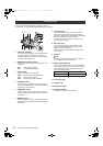
29. HD SDI B connector
This connector is for outputting video. A video signal
based on the setting of the 15. HD SDI A · B switch is
output. The video signal is the same as that output from
the 17. HD SDI A connector.
AJ-HPX2700G-VQT1V27_eng.book 21 ページ 2008年9月2日 火曜日 午後5時43分