


24
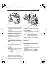
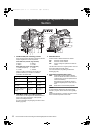
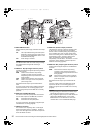
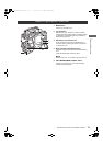
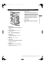
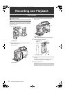
Parts and their Functions: Time Code Section
1. GENLOCK IN connector (BNC)
This connector is used to input a reference signal before
the camera unit is gen-locked, or before the time code is
externally locked.
2. TC IN connector (BNC)
This connector is used to input a reference time code
when you externally lock the time code.
3. TC OUT connector (BNC)
When you inter-lock the time code of unit with that of an
external device this must be connected with the time
code input (TC IN) connector of the external device.
Note
The time code must be input in the same format as the
system mode of the unit.
4. HOLD button
Pressing this button freezes the time data indication on
the counter. Note that time code generation continues.
Pressing the button again reactivates the counter.
This function is used to ascertain the time code or CTL
count of a particular recorded scene.
5. RESET button
This button resets the time data (CTL) on the counter to
“00:00:00:00”.
If this button is pressed when with the 7. TCG switch
positioned at [SET], time code and user bits data are
reset to 0, and real-time data is reset to the initial value.
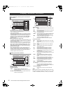
6. DISPLAY (counter display selector) switch
Indications of the time code, CTL and user bits on the
counter of the display window depend on the positions
of this switch and the 7. TCG switch.
Pressing the 4. HOLD button also displays Date/Time/
Time Zone.
UB: User bits, DATE, TIME or Time zone
indicated.
TC: Time code indicated.
CTL: CTL indicated.
7. TCG (time code selector) switch
This switch is used to specify the stepping mode for the
built-in time code generator.
F-RUN: Select this position to continuously advance
the time code independently of the P2 card
recording status.
Use this mode to synchronize the time code
with the time of day, or to externally lock the
time code.
SET: Select this position to set the time code and/or
user bits.
R-RUN: Select this position to advance the time code
only during recording.
For spliced scenes recorded on P2 cards, the
sequence of time codes is unbroken.
Note
When VFR is used during native recording, VFR is
carried out with fixed R-RUN even when F-RUN has
been set.
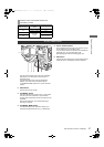
8. Cursor and SET buttons
Use these buttons to set the time code and user bits.
The 4 triangular buttons are the cursor buttons, and the
center rectangular one is the SET button.
For guidance in setting the time code and user bits, see
[Setting Time Data] (page 60).
Time Code Section
13
2
4
5
6
7
8
AJ-HPX2700G-VQT1V27_eng.book 24 ページ 2008年9月2日 火曜日 午後5時43分