


67
Adjustments and Settings for Recording
: Setting Time Data
Adjustments and Settings for Recording
The unit’s internal time code generator can be locked to an
external generator. In addition, the external time code
generator can be locked to the unit’s internal generator.
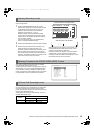
As the figure shows, connect both the reference video signal
and reference time code.
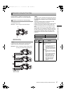
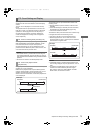
Example 1: When locking onto an external signal
a. Reference time code
b. Reference video signal
Note
In place of the HD Y reference signal, composite video
signals can be input as the reference video signal.
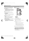
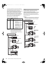
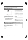
Example 2: When connecting a multiple number of units
and using one of them as the reference unit
c. MON OUT (VBS)
Note
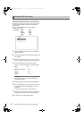
The system can be configured with multiple units by opening
the <GENLOCK> screen from the SYSTEM SETTING page
and setting the GL PHASE item to the connector using menu
operations.
The phase of the time code can correspond to the VBS
output signals of the MON OUT connector.
However, the same value should commonly be set to the GL
PHASE for all cameras. If different values coexist in the
system, the shooting timing may not correspond to each
other.
Note that when the unit is in the 1080-23.98PsF or 1080-
24PsF modes, it is not possible to lock the time code using
the VBS connection with one unit as a reference unit in the
manner shown in Example 2. When using these modes,
connect the unit in the manner shown in Example 4 and
Example 6.
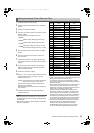
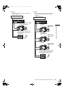
Externally Locking the Time Code
Example of connections for external locking
GENLOCK IN
TC IN
a
b
GENLOCK IN
TC IN
TC OUT
GENLOCK IN
TC IN
TC OUT
TC OUT
c
c
c
Reference unit
To the next camera
Reference video signal Setting of GL PHASE
MON OUT (VBS) COMPOSIT
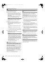
Setting of GL PHASE
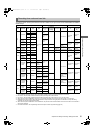
Item
Variable
range
Remarks
GL PHASE HD SDI
COMPOSIT
For selecting the output signals that lock
phases to the signals that are input in the
GENLOCK IN connector.
HD SDI:
For locking the HD SDI signals
to the GENLOCK input.
For the down converter output
signals, the start position of the
video delays by about 90 lines.
COMPOSIT:
For locking the down converter
output signals to the GENLOCK
input.
For the HD SDI output signals,
the start position of the video
gains by about 90 lines.
Note, however, that in 1080-
23.98PsF mode and 1080-
24PsF mode, the phase is
locked to HD SDI even if
“COMPOSIT” has been
selected.
AJ-HPX2700G-VQT1V27_eng.book 67 ページ 2008年9月2日 火曜日 午後5時43分