


-9-
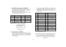
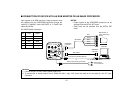
Pin No. Signal Pin No. Signal
1 Composite Video Output 11 RCB Transmission
2 GND 12 Control (Command)
3 G/Y/Y Output 13 +9.2 V RCB
4 R/PR/C Output 14 DC 12 V Output
5 GND 15 DC 12 V Input
6 RCB Detect 16 DC 12 V Input
7 EXT SUB In 17 RCB Reception
8 B/PB Output 18 GND
9 GND 19 GND
10 G/L Input 20 Not used
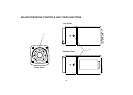
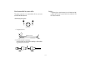
<Front View>
Remote Connector (REMOTE)
<Front View>
DC Input Connector (EXT DC IN)
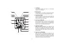
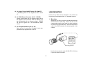
10. Remote Connector (REMOTE)
Input terminal dedicated to control signals from the
optional Remote Control Box (WV-CB700A) and the
Remote Control Unit (WV-RC700A).
* WV-CB700A is connected through the optional con-
version cable (WV-CA20T10).
* WV-RC700A is connected through the optional con-
version cable (WV-CA26T20).
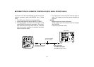
11. Power Indicator
Red LED lamp lights to indicate that the specified DC
power is supplied to the camera.
12. DC Input Connector (EXT DC IN)
12 V DC is supplied through the 4-pin connector pro-
vided with the camera.
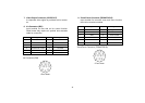
Pin No. Signal
1 +12 V In
2 +12 V In
3 Ground
4 Ground
o
q
i
w
u
e
yt
r
!2
!0
!1!3!4!5!6
@0!9!8!7
r
e
w
q