


-20-
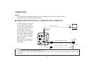
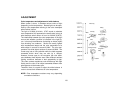
CONNECTION OF COMPUTER INTERFACE ADAPTOR
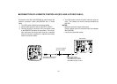
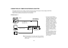
The system shown here can remotely control this camera by using the Computer Interface Adaptor WJ-PC500.
The software required for this operation should be obtained locally.
Please contact qualified service personnel for this software.
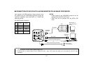
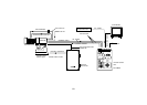
PC Mode System 1-1
CAMERA 2
IN
MONITOR
OUT
G/L IN
CAMERA 1 IN
DC12V IN
CAMERA SELECT
RS-232C/422
ZOOM/FOCUS
REMOTE
EXT DC IN
PAGE
ITEM
(AWC)
UP
(ABC)
DOWN
(BAR)
IRIS
SEE MANUAL
CAUTION
CONNECT TO SPECIFIED
CLASS 2 POWER SUPPLY
ONLY SEE MANUAL
VBS/HD
75
VD
VIDEO/RGB
CONTROL
VIDEO OUTG/L IN
ON
OFF
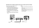
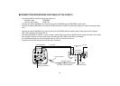
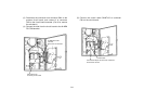
• Connect the WV-CA20T10
Conversion Cable and WV-CA
10B02, WV-CA10B25 or WV-
CA10B50 10/10-pin Cable
between the Camera 1 Input
Connector on the Computer
Interface Adaptor and Remote
Connector of this camera.
• Connect the coaxial cable
between the Monitor Output
Connector on the Computer
Interface Adaptor and the
video input connector of the
monitor.
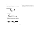
• Connect the 25/9-pin conver-
sion cable between the RS-
232C/422 Connector on the
Computer Interface Adaptor
and computer.
25/9-pin Conversion Cable
for RS232C (straight)
Conversion Cable
WV-CA20T10 (1m)
Computer
Monitor
AW-E560
WJ-PC500
WV-CA10B02 (2m)
WV-CA10B25 (25m)
WV-CA10B50 (50m)
Note: The decrement of the video signal from the Monitor
Output Connector on this Unit is in proportion to the
cable length.