-24-
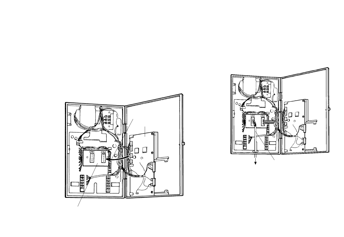
(3) Disconnect the connector from connector CN4 on the
process circuit board, and connect it to connector
CN2 on the circuit board mounted. (Cut off or remove
the wire band.)
(4) Connect the lead from the circuit board to the ALARM
DC COM terminal.
(5) Connect the control cable CA28T103 to connector
CN1 on the circuit board.
ALARM DC COM
terminal
Circuit board, an
accessory to the cable
Process circuit board
Connect the 28-pin end of it to the control ter-
minal on the camera.
Control cable


