


-10-
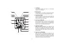
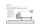
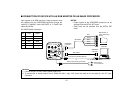
13. Video/RGB Output Connector (VIDEO/RGB)
Composite/Y signal, RGB/Y-C/component signal and
synchronizing signal are output from this connector.
* Refer to Page 41 for signal selection.
The optional cable WV-CA9T5 or WV-CA9T9 must be
used for connection to this connector.
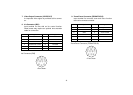
Pin No. Signal Pin No. Signal
1 GND 6 SY/COMP
2 GND 7 SYNC
3 R/PR/C 8 GND
4 G/Y/Y 9 C/NC
5 B/PB/NC
<Front View>
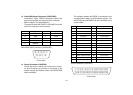
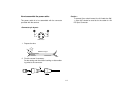
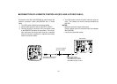
The multiplex adaptor WV-PS550 is connected to this
connector when using a coaxial multiplex system. The
WV-RC700A and WV-PS550 can be connected with a
coaxial cable.
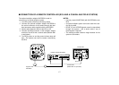
Pin No. Signal Pin No. Signal
1 Composite Video Output 15 Defroster Control Output
2 GND 16 Wiper Control Output
3 Not Used 17 Common
4 Not Used 18 +5.2 V Output
5 G/L Input 19 GND
6 GND 20 −5.2 V Output
7 WV-PS550 Detect 21 GND
8 PS Transmission 22 GND
9 PS Reception 23 DC 12 V Input
10 GND 24 DC 12 V Input
11 UP Control Output 25 Not Used
12 Down Control Output 26 +9.2 V Output
13 Left Control Output 27 GND
14 Right Control Output 28 GND
<Front View>
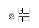
Control Connector (CONTROL)
Video/RGB Output Connector (VIDEO/RGB)
14. Control Connector (CONTROL)
Control signals for a pan/tilt unit come to this connec-
tor when a pan/tilt unit controller is connected to the
camera through the Remote Control Unit WV-RC700A
with a multicable.
⁄4⁄3⁄2⁄1⁄0.,mnbcxz
¤8¤7¤6¤5¤4¤3¤2¤1¤0⁄9⁄8⁄7⁄6⁄5
v
o
q
i
w
u
e
y
tr