


English _21
● INSTALLATION & CONNECTION
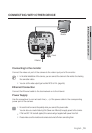
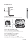
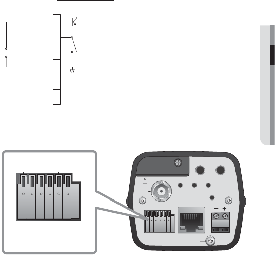
Alarm I/O Wiring Diagram
ALARM IN
ALARM OUT
ALARM COM
GND
RXTX+
RXTX-
1
2
3
4
5
6
(5mA sink)
(30VDC 2A,
125VAC 0.5A MAX)
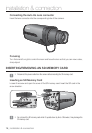
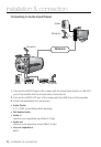
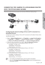
Connecting to the I/O port box
Connect the Alarm I/O signal to the corresponding port of the rear port box.
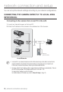
AUDIO OUT
VIDEO
SD SYSTEM POWER
RESET
NETWORK
ACT
LINK
GND
1 : ALARM IN 4 : GND
2 : ALARM OUT 5 : RS-485+
3 : ALARM COM 6 : RS-485-
1 2 3 4 5 6
AC 24V
DC 12V
AUDIO IN
SD CARD
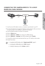
1 : ALARM IN 4 : GND
2 : ALARM OUT 5 : RS-485+
3 : ALARM COM 6 : RS-485-
1 2 3 4 5 6
ALARM IN : Used to connect the alarm input signal.
ALARM OUT : Used to connect the alarm output signal.
ALARM COM : Common port where the alarm output signal is connected.
GND : Used for earth-grounding.
RS-485+ : Communication port for RS-485 receiver (+).
RS-485- : Communication port for RS-485 receiver (–).
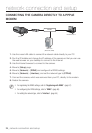
Connecting an external RS-485 device
Connect the camera with an external device using the [RS-485 +, -] ports.
You can control the pan/tilt operations of the camera via RS-485 communications.
•
•
•
•
•
•