


Connections
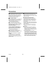
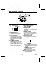
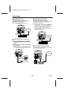
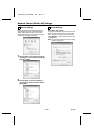
Connecting to a LAN
Use an Ethernet cable to connect the
ETHERNET connector of the camera to the
LAN’s Ethernet switching hub.
☞
Use a straight-type Ethernet cable.
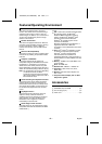
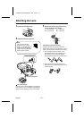
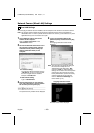
Connecting to Alarm Terminals
1
Connect an infrared sensor or similar to
the ALARM IN terminal at the rear of the
camera.
2
Connect a buzzer or lamp to the ALARM
OUT terminal.
Once the connections are complete, install
the supplied ferrite core A to the power cord.
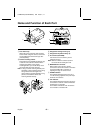
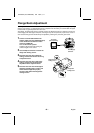
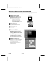
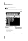
Connecting to the Internet
Use an Ethernet cable to connect the
ETHERNET connector of the camera to a device
such as a router or ADSL modem that is
connected to the Internet.
☞
If connecting to a router, use a straight-type
Ethernet cable. If connecting to an ADSL
modem or to some other type of device, refer
to the documentation provided with the
device for details on what type of connection
method should be used.
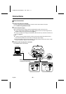
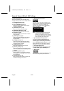
Connecting to the PPP (Dial up)
Connect as follows if connecting to the provider
by means of a telephone line.
PC CARD
RS-232C
ALARMIN OUT
MODEM
PC
COM
AC24V
DC12V
GND
1 2
ETHERNET
POWER
MONITOR
OUT
Ethernet cable
(straight type)
Ethernet switching hub
LAN
CLASS 2 WIRING
PC CARD
RS-232C
ALARMIN OUT
MODEM
PC
COMD/N IN
AC24V
DC12V
GND
1 2
ETHERNET
POWER
MONITOR
OUT
Infrared sensor or similar
Buzzer or lamp
CLASS 2 WIRING
A
PC CARD
RS-232C
ALARMIN OUT
MODEM
PC
COM
AC24V
DC12V
GND
1 2
ETHERNET
POWER
MONITOR
OUT
Internet
Ethernet cable
(straight type)
Device such as router or ADSL modem
CLASS 2 WIRING
CLASS 2 WIRING
PC CARD
RS-232C
ALARMIN OUT
MODEM
PC
COMD/N IN
AC24V
DC12V
GND
1 2
ETHERNET
POWER
MONITOR
OUT
MODEM
PC
1 2
Internet
Serial cable
Set switch 1 to “MODEM”
Modem
L5AM2/XE (VCC-WB4000P) GB 2004, 2, 17
– 10 –
English