


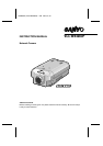
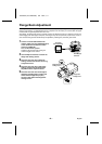
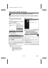
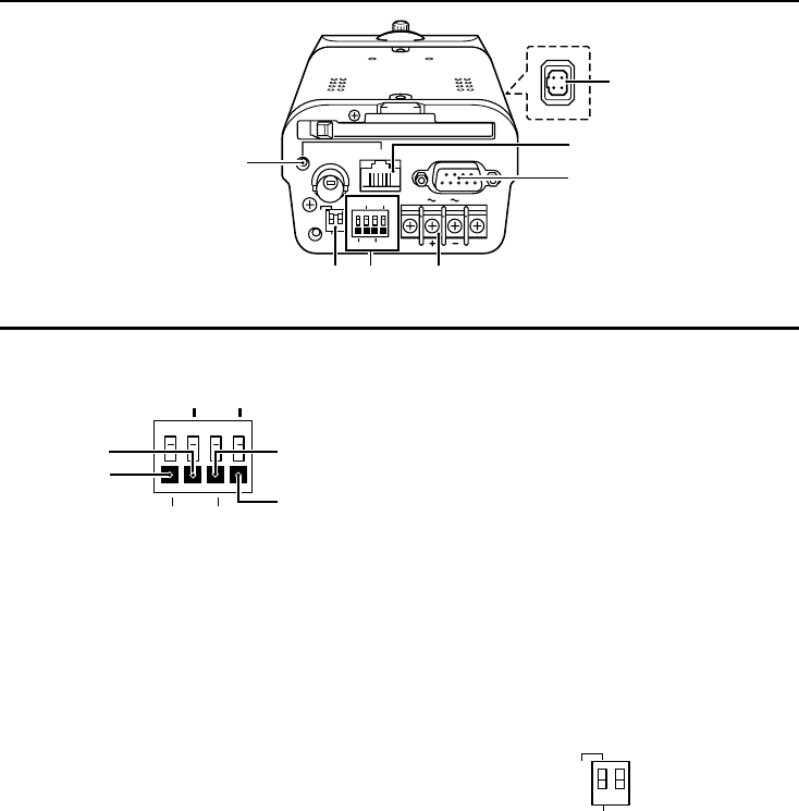
Name and Function of Each Part
CLASS 2 WIRING
PC CARD
RS-232C
ALARM IN OUT
MODEM
PC
AC24V
DC12V
GND
1 2
ETHERNET
POWER
MONITOR
OUT
8
H
G
JF
I
9
COMD/N IN
9
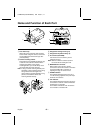
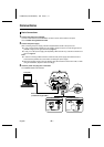
Alarm, Day/Night terminals
A
ALARM IN terminal (IN)
Connect this terminal to an infrared
sensor or similar use in external detection
of intruders.
B
D/N IN terminal (D/N IN)
This can only be used when COLOR
mode is set. A device such as an infrared
sensor can be used to automatically
switch between color images and black &
white images.
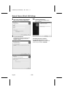
C
ALARM OUT terminal (OUT)
Connect this terminal to a buzzer or lamp
that is used to warn when an alarm is
detected by means of motion sensor or
alarm input. In addition, when the day/night
function (COLOR mode or TIMER mode) is
being used, an IR lamp or other device can
be made to illuminate when monitoring
switches to black & white images. (Output
rating: 18 V, 25 mA)
D
Ground terminal (COM)
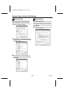
F
Power supply input terminals
(AC24V, DC12V, GND)
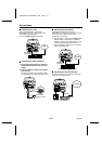
G
RS-232C connector
Use this connector to connect the camera to
a modem for transmission of data along
telephone lines, or for connecting the camera
to a computer.
H
ETHERNET connector
Use this connector to connect the camera
directly to a computer or to a network. Use a
10Base-T or 100Base-TX (Category 5, UTP)
cable to make the connection.
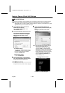
I
Lens iris output connector
Connect this connector (4-pin socket) to the
lens iris plug of the automatic iris-type lens
(sold separately).
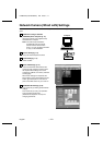
J
Communication setting switches
Switch 1: Communication setting
(PC/MODEM)
•
PC: Use this switch to set the function of
the RS-232C connector when connecting
the camera directly to either a modem or
computer.
•
MODEM: With a PPP connection the
data transfer is switched.
Switch 2: This switch has no function.
Note: Make sure that the camera’s power is
turned off before setting the function of
the RS-232C connector.
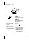
ALARM IN OUT
A
B
C
D
COMD/N IN
MODEM
PC
1 2
L5AM2/XE (VCC-WB4000P) GB 2004, 2, 17
– 6 –
English