


Chapter 2 Operation 29
(GB)
Chapter 2
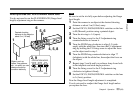
Selection
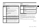
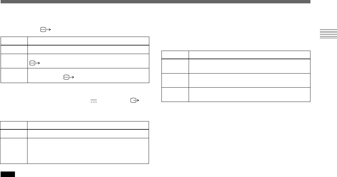
IN
OUT
Function
Functions as the input connector.
Functions as the output connector.
Select the output signal with the SIGNAL setting.
HD/VD: Outputs the HD/VD signal.
C. SYNC: Outputs the composite sync signal.
Selection
OFF
G
RGB
Function
No sync signal is added to an output signal.
Adds a sync signal to the G signal output from the
RGB/SYNC connector.
Adds sync signals added to the G, B and R signals
output from the RGB/SYNC connector.
RGB SYNC
Adds a sync signal to the G signal or R, G and B signals
output from the RGB/SYNC connector.
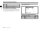
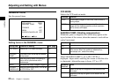
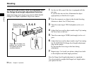
12P CONNECTOR
Switches the input and output of the DC IN/VBS
connector (12-pin). Selects the output signal from this
connector when OUT is selected.
Note
When the CMA-D3/C3CE is connected to the camera with
the CCMC-3MZ connecting cable, you cannot set this item.
Switch between input and output with the IN/OUT switch
on the CMA-D3/D3CE camera adaptor.
For details, refer to the operating instructions of the CMA-
D3/D3CE.
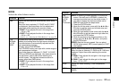
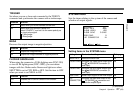
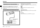
Selection
H.PHASE
SC.PHASE
ROUGH
SC.PHASE
FINE
Function
Adjusts the horizontal phase within the range from
–20 to +127.
Roughly adjusts the subcarrier phase by setting to 0°
or 180°.
Finely adjusts the subcarrier phase within the range
from –127 to +127.
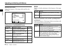
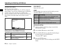
VBS lock
Appears only when an external reference sync signal (VBS
signal) is input. Adjusts the horizontal phase and SC
(subcarrier) phase to synchronize the camera operation with
the reference signal.
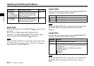
HD/VD lock
Appears only when an external reference sync signal (HD/
VD signal) is input. Adjusts the horizontal phase to
synchronize the camera operation with the reference signal.
Select H.PHASE, then adjust the level within the range
from –20 to +127.