


50 (GB) Chapter 3 Installation and Connections
Chapter 3
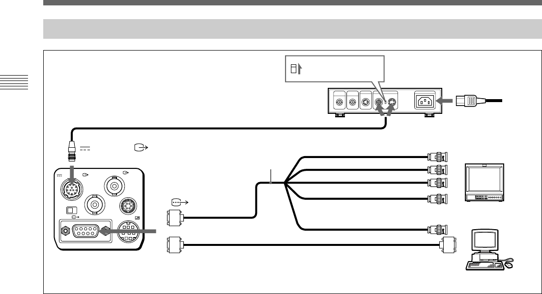
Basic System Connection
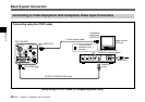
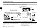
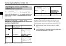
Connecting to Video Equipment with RGB or S-Video Inputs
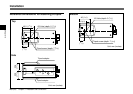
VIDEO OUT
DC IN/VBS
REMOTE
LENS
TRIG IN
MENU LOCK
OFF ON
RGB/SYNC
1
2
DXC-390/390P
DC IN/VBS
CCDC-5/10/25/50A/100A cable or
CCMC-12P02/05/10/25 cable*
Camera cable: CCXC-9DB (D-sub 9-pin
y BNC connectors), or CCMC-9DS (D-
sub 9-pin y BNC, S-video connectors)
RGB/SYNC
or
Camera cable CCXC-9DD
(D-sub 9-pin y D-sub 9-pin)
Set the MODE s
elector
to the “1” position
.
CMA-D2/D2MD/D2CE/
D2MDCE camera adaptor
CAMERA (4-pin or 12-pin)
R input
G input
B input
Sync input
1)
Composite video (BNC) or
S-video input (4-pin)
2)
Computer, image
processor etc.
RGB monitor,
image processor,
etc.
*If a CCMC cable is used, the S-video signal is also output from the S-video output of the CMA-D2/D2MD/D2CE/D2MDCE.
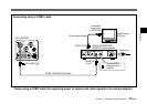
1) When using a video monitor without a sync signal input connector, the
camera can be set to output a sync signal with the G signal or RGB
signals.
For details, see “SYSTEM menu” on page 27.
2) This setup is for connecting to a composite video (VBS) connector. To
output separated Y/C signals to the S-video input of video equipment,
use a CCMC-9DS camera cable.
For details on switching camera output between VBS (composite video) and
Y/C, see “SYSTEM menu” on page 27.
RGB/SYNC input
Power cord