


Chapter 3 Installation and Connections 51
(GB)
Chapter 3
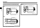
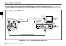
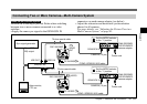
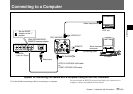
Connecting Two or More Cameras—Multi-Camera System
Notes on multi-camera system
Perform the following to prevent flicker when switching
between two or more cameras connected to a video
switcher:
• Supply the same sync signal to the GENLOCK IN
connectors on each camera adaptor (see below).
• Adjust the subcarrier and horizontal synchronization
phases for all cameras.
For more details, see “Adjusting the Picture Tone in a
Multi-Camera System” on page 41.
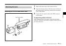
VIDEO OUT
DC IN/VBS
REMOTE
LENS
TRIG IN
MENU LOCK
OFF ON
RGB/SYNC
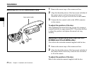
VIDEO OUT
DC IN/VBS
REMOTE
LENS
TRIG IN
MENU LOCK
OFF ON
RGB/SYNC
1
2
1
2
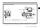
Sync signal generator
Sync (VBS or
BS) output
VBS OUT
Switcher, etc.
VIDEO IN
VBS OUT
VIDEO IN
Video monitor,
VTR, etc.
75-ohm coaxial cable
DXC-390/390P
VIDEO
OUT
DC IN/VBS
CCMC-12P02/05/10/25 cable
GENLOCK IN
CAMERA (12-pin)
Set the MODE selector
to the “1” position.
CMA-D2/D2MD/
D2CE/D2MDCE
camera adaptor
CMA-D2/D2MD/
D2CE/D2MDCE
camera adaptor
Power cord
Power cord
75-ohm coaxial cable
Set the MODE selector
to the “1” position.
CCMC-12P02/05/10/25 cable
DXC-390/390P
VIDEO
OUT
GENLOCK IN
CAMERA (12-pin)
DC IN/VBS