


24
Location and Function of Parts
Chapter 1 Overview
Even when you are recording or playing back HD 23.98P
signals, 23.98PsF signals are not output from this
connector. The output is 59.94i signals after 2-3 pulldown.
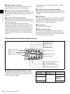
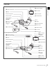
c VIDEO OUT (video output) connector (BNC type)
Outputs a video signal for a video monitor. The output
signal is composite or HD Y. When the output signal is
composite, setting menus, timecode, or shot data can be
superimposed on the camera output video depending on
the menu settings, and you can view them on the monitor
screen. To lock the timecode of an external device to the
timecode of this unit, connect the genlock signal input
connector of the external device to this connector.
• The subcarrier phase cannot be adjusted.
• Even when you are recording or playing back HD
23.98P signals, 23.98PsF signals are not output from this
connector. The output is 59.94i signals after 2-3
pulldown.
You can select the composite or HD Y signal output on the
OUTPUT page of the OPERATION menu. For details, see
“Selecting the Output Signals” on page 140.
d TC OUT (timecode output) connector (BNC type)
To lock the timecode of an external VTR to the timecode
of this unit, connect this connector to the external VTR’s
timecode input connector.
e TC IN (timecode input) connector (BNC type)
To apply an external lock to the timecode of this unit, input
the reference timecode.
For details of timecode, see “To set the timecode” on
page 66.
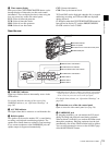
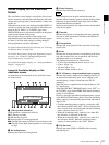
Rear
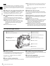
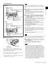
a TALLY (back tally) indicator (red)
Lights up during recording. It will not light if the TALLY
switch (see below) is set to OFF. This indicator also flashes
to indicate warnings (see page 19) in the same manner as
the REC/TALLY indicator in the viewfinder.
For details, see “Operation Warnings” on page 165.
b TALLY switch
Set to ON to activate the TALLY indicator (see above)
function.
c Battery attachment shoe
Attach a BP-GL95/GL65/L60S/L80S Battery Pack.
Alternatively, you can attach an AC-DN2B/DN10 AC
Adaptor to operate the camcorder on AC power supply.
For details about how to attach the battery or AC adaptor,
see “Preparing a Power Supply” on page 36. For
information about attaching a synthesized tuner, see
“Attaching a UHF Synthesized Tuner” on page 47.
For your safety, and to ensure proper operation of the
camcorder, Sony recommends the use of the following
battery packs: BP-GL95, BP-GL65, BP-L60S, and BP-
L80S.
d WRR connector (7-pin)
Connect a CA-WR855 Camera Adaptor with attached
WRR-855 UHF Synthesized Tuner.
For details, see “Attaching a UHF Synthesized Tuner” on
page 47.
Note
F350
Notes
F350
F350
Note
1 TALLY indicator
2 TALLY switch
3 Battery attachment
shoe
4 WRR connector
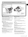
1 Connector panel
!"##$%&'#$()*