


25
Location and Function of Parts
Chapter 1 Overview
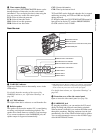
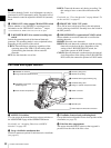
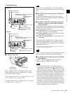
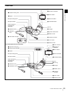
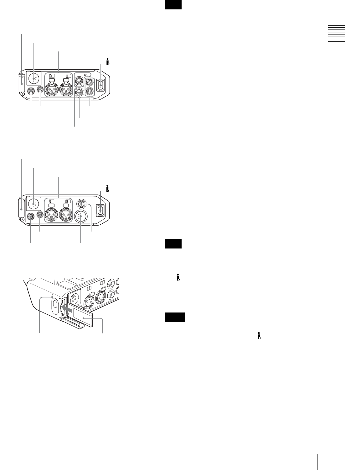
1 Connector panel
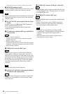
a “Memory Stick” slot
Insert a “Memory Stick”. The “Memory Stick” access
indicator lights up when the “Memory Stick” is being
accessed for reading or writing.
For details about how to insert a “Memory Stick”, see “To
insert a “Memory Stick”” on page 146.
For details about the types of “Memory Stick”, see “About
a “Memory Stick”” on page 174.
Do not remove a “Memory Stick” while the “Memory
Stick” access indicator is lit. Doing so may cause a loss of
data.
b DC IN (DC power input) connector (XLR type, 4-
pin, male)
To operate the camcorder using an AC power supply,
connect an AC-550 AC Adaptor with the DC output cable
supplied with the adaptor.
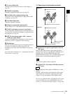
c AUDIO IN CH-1/CH-2 (audio input channel 1/2)
connectors (XLR type, 3-pin, female) and input
selection switches
Connect other audio equipment or external microphone.
Set the input selection switches as shown below according
to the microphone or equipment.
LINE (left position): For connecting an external audio
signal source such as a stereo amplifier
MIC (center position): For connecting any microphone
other than 48 V microphone
MIC +48V ON (right position): For connecting a 48 V
microphone
Signals input to the AUDIO IN CH-1 connector can be
recorded on audio channels 1 and 3. Similarly, signals
input to the AUDIO IN CH-2 connector can be recorded on
audio channels 2 and 4.
1)
1) When the AUDIO IN (CH-1/CH-2/CH-3/CH-4) switches on the side
control panel are set to “REAR” or “R”.
If MIC +48V ON is selected for a microphone other than
48 V microphone, the microphone may be damaged.
d (i.LINK) DV OUT S400 connector (6-pin, IEEE
1394 compliant)
Connect to a device supporting the DV format or a
computer, using an i.LINK cable (DV cable).
• If video and audio signals are not output from the
external device connected to the (i.LINK) DV OUT
S400 connector, disconnect the i.LINK cable (DV cable)
and then reconnect it, making sure that it is firmly seated.
• When you connect the camcorder and other equipment,
such as a hard disk drive, with an i.LINK interface to a
computer with i.LINK connectors, turn off the power of
the computer, the other equipment, and the camcorder
before connecting them using the i.LINK cable (DV
cable). If a bus-powered type
1)
hard disk drive or similar
equipment is connected while the computer is powered
on, electric current flows into the camcorder because of
the high voltage caused by the load shift of the computer
power, and this may cause a malfunction.
1 ”Memory Stick” slot
2 DC IN connector
3 AUDIO IN CH-1/CH-2 connectors and
input selection switches
1 “Memory Stick” slot
2 DC IN connector
3 AUDIO IN CH-1/CH-2 connectors and
input selection switches
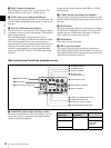
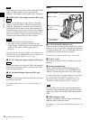
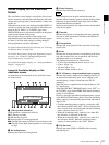
5 REMOTE
connector
6 DC OUT 12V
connector
7 TC connector and IN/OUT
selector switch
8 VIDEO OUT connector
9 AUDIO OUT CH-1/CH-2
connectors
5 REMOTE
connector
6 DC OUT 12V
connector
0 AUDIO OUT connector
qa HDSDI OUT connector
PDW-F330
PDW-F350
4 DV OUT S400
connector
4 DV OUT S400
connector
“Memory Stick”
access indicator
“Memory Stick”
Note
Note
Notes