


Chapter 2: Installation
2-9
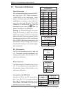
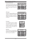
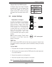
NIC2 (LAN2) LED
The LED connections for LAN2 are on pins
9 and 10 of JF1. Attach LAN LED cables to
display network activity. See the table on the
right for pin defi nitions.
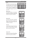
HDD LED
The HDD LED connection is located on pins
13 and 14 of JF1. Attach the hard drive LED
cable here to display disk activity (for any
hard drives on the system, including SAS,
Serial ATA and IDE). See the table on the
right for pin defi nitions
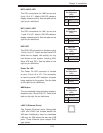
NIC1 LED
Pin Defi nitions
(JF1)
Pin# Defi nition
11 Vcc
12 Ground
NIC2 LED
Pin Defi nitions
(JF1)
Pin# Defi nition
9 Vcc
10 Ground
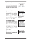
NIC1 (LAN1) LED
The LED connections for LAN1 are on pins
11 and 12 of JF1. Attach LAN LED cables to
display network activity. See the table on the
right for pin defi nitions.
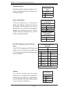
Power On LED
The Power On LED connector is located
on pins 15 and 16 of JF1. This connection
is used to provide LED indication of power
being supplied to the system. See the table
on the right for pin defi nitions.
Power LED
Pin Defi nitions
(JF1)
Pin# Defi nition
15 5V Stby
16 Control
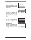
NMI Button
The non-maskable interrupt button header is
located on pins 19 and 20 of JF1. Refer to the
table on the right for pin defi nitions.
NMI Button
Pin Defi nitions
(JF1)
Pin# Defi nition
19 Control
20 Ground
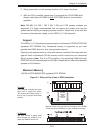
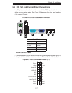
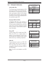
LAN1/2 (Ethernet Ports)
Two Gigabit Ethernet ports (designated
LAN1 and LAN2) are located beside the
VGA port. Additionally, there is a dedicated
LAN poor for IPMI above the two rear USB
ports. These Ethernet ports accept RJ45
type cables.
HDD LED
Pin Defi nitions
(JF1)
Pin# Defi nition
13 Vcc
14 HD Active