


H8DI3+/I+(-F) Serverboard User's Manual
2-18
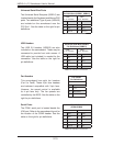
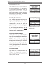
SATA Ports
There are no jumpers to confi gure the SATA
ports, which are designated SATA0 through
SATA5. See the table on the right for pin
defi nitions.
SATA Ports
Pin Defi nitions
(SATA0-SATA3)
Pin # Defi nition
1 Ground
2 TXP
3 TXN
4 Ground
5 RXN
6 RXP
7 Ground
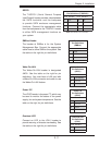
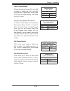
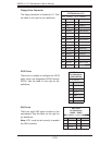
Floppy Drive Connector
The fl oppy connector is located at J17. See
the table on the right for pin defi nitions.
Floppy Drive Connector
Pin Defi nitions (J17)
Pin# Defi nition Pin # Defi nition
1 Ground 2 FDHDIN
3 Ground 4 Reserved
5 Key 6 FDEDIN
7 Ground 8 Index
9 Ground 10 Motor Enable
11 Ground 12 Drive Select B
13 Ground 14 Drive Select B
15 Ground 16 Motor Enable
17 Ground 18 DIR
19 Ground 20 STEP
21 Ground 22 Write Data
23 Ground 24 Write Gate
25 Ground 26 Track 00
27 Ground 28 Write Protect
29 Ground 30 Read Data
31 Ground 32 Side 1 Select
33 Ground 34 Diskette
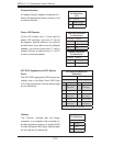
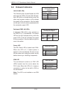
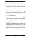
SAS Ports
Pin Defi nitions
(SAS0 ~ SAS7)
Pin# Defi nition Pin # Defi nition
1 Ground 2 TXP
3 TXN 4 Ground
5 RXN 6 RXP
7 Ground
SAS Ports
There are eight SAS ports included on the
serverboard. See the table on the right for
pin defi nitions.
Note: JPS1 must be set correctly to enable
the SAS controller.