


Chapter 2: Installation
2-13
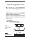
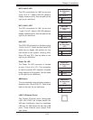
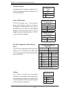
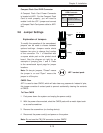
Compact Flash Card PWR Connector
A Compact Flash Card Power Connector
is located at JWF1. For the Compact Flash
Card to work properly, you will need to
enable it with the JCF1 jumper and connect
a Compact Flash Card power cable to JWF1
fi rst.
2-8 Jumper Settings
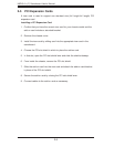
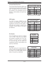
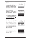
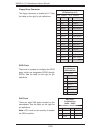
Explanation of Jumpers
To modify the operation of the serverboard,
jumpers can be used to choose between
optional settings. Jumpers create shorts
between two pins to change the function
of the connector. Pin 1 is identifi ed with
a square solder pad on the printed circuit
board. See the diagram at right for an
example of jumping pins 1 and 2. Refer
to the serverboard layout page for jumper
locations.
Note: On two-pin jumpers, "Closed" means
the jumper is on and "Open" means the
jumper is off the pins.
Connector
Pins
Jumper
Setting
3 2 1
3 2 1
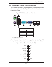
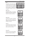
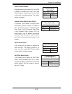
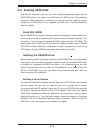
CMOS Clear
JBT1 is used to clear CMOS, which will also clear any passwords. Instead of pins,
this jumper consists of contact pads to prevent accidentally clearing the contents
of CMOS.
To Clear CMOS
First power down the system and unplug the power cord(s).1.
With the power disconnected, short the CMOS pads with a metal object such 2.
as a small screwdriver.
Remove the screwdriver (or shorting device).3.
Reconnect the power cord(s) and power on the system.4.
Note: Do not use the PW_ON connector to clear CMOS.
JBT1 contact pads
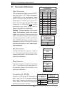
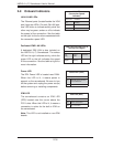
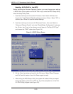
Compact Flash Card
PWR Connector
Jumper Defi nition
On Compact Flash
Power On (Default)
Off Compact Flash
Power Off