


Chapter 2: Installation
2-17
2-10 Floppy, SAS and SATA Drive Connections
Use the following information to connect the IDE hard disk drive cables.
A red mark on a wire typically designates the location of pin 1.
•
The 80-wire ATA100/66 IDE hard disk drive cable that came with your system •
has two connectors to support two drives. This special cable should be used
to take advantage of the speed this new technology offers. The blue connector
connects to the onboard IDE connector interface and the other connector(s) to
your hard drive(s). Consult the documentation that came with your disk drive for
details on actual jumper locations and settings for the hard disk drive.
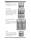
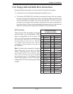
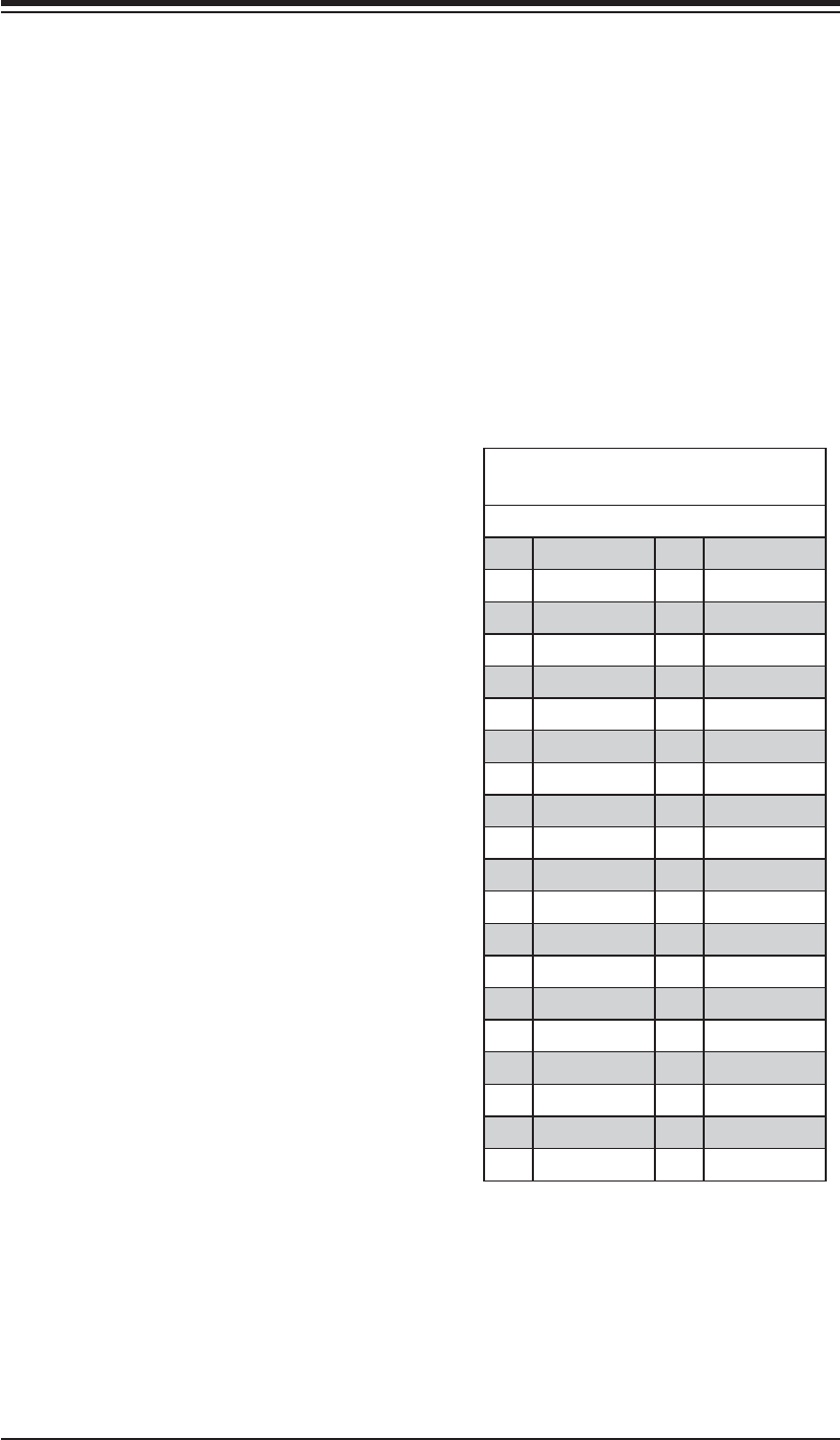
IDE Drive Connector
Pin Defi nitions (IDE#1)
Pin# Defi nition Pin # Defi nition
1 Reset IDE 2 Ground
3 Host Data 7 4 Host Data 8
5 Host Data 6 6 Host Data 9
7 Host Data 5 8 Host Data 10
9 Host Data 4 10 Host Data 11
11 Host Data 3 12 Host Data 12
13 Host Data 2 14 Host Data 13
15 Host Data 1 16 Host Data 14
17 Host Data 0 18 Host Data 15
19 Ground 20 Key
21 DRQ3 22 Ground
23 I/O Write 24 Ground
25 I/O Read 26 Ground
27 IOCHRDY 28 BALE
29 DACK3 30 Ground
31 IRQ14 32 IOCS16
33 Addr1 34 Ground
35 Addr0 36 Addr2
37 Chip Select 0 38 Chip Select 1
39 Activity 40 Ground
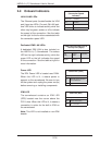
IDE Connectors
There are two IDE connectors (one blue
and one white) on the serverboard. IDE#1
(blue) is designated as the Primary IDE
drive. The white connector is designated as
the Secondary IDE drive and is reserved
for Compact Flash Card use only. (See the
note below.) See the table on the right for
pin defi nitions.
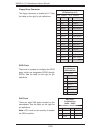
Note: The white slot is reserved for Compact
Flash Cards only. Do not use it for other
devices. If populated with a Compact Flash
Card, IDE#1 (the blue slot) will be available
for one device only. For the Compact Flash
Card to work properly, you will fi rst need to
enable with JCF1 and connect a power cable
to JWF1.