


H8DI3+/I+(-F) Serverboard User's Manual
2-12
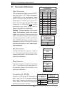
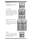
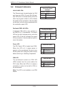
Chassis Intrusion
A Chassis Intrusion header is located at JL1.
Attach the appropriate cable to inform you of
a chassis intrusion.
Chassis Intrusion
Pin Defi nitions
(JL1)
Pin# Defi nition
1 Battery voltage
2 Intrusion signal
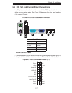
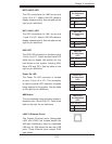
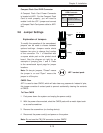
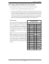
ATX PS/2 Keyboard and PS/2 Mouse
Ports
The ATX PS/2 keyboard and PS/2 mouse are
located next to the Back Panel USB Ports
0~3 on the serverboard. See the table at right
for pin defi nitions.
PS/2 Keyboard/Mouse Pin
Defi nitions
PS2 Keyboard PS2 Mouse
Pin# Defi nition Pin# Defi nition
1 KB Data 1 Mouse Data
2 No
Connection
2 No
Connection
3 Ground 3 Ground
4 Mouse/KB
VCC (+5V)
4 Mouse/KB
VCC (+5V)
5 KB Clock 5 Mouse Clock
6 No
Connection
6 No
Connection
VCC: with 1.5A PTC (current limit)
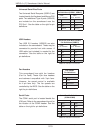
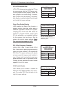
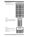
Power LED/Speaker
On the JD1 header, pins 1~3 are used for
power LED indication, and pins 4-7 are for
the speaker. See the tables on the right for
pin defi nitions. If you wish to use the onboard
speaker, you should close pins 6~7 with a
jumper. Connect a cable to pins 4~7 of JD1
to use an external speaker.
Speaker Connector
Pin Defi nitions
Pin Setting Defi nition
Pins 4~7 External Speaker
Pins 6~7 Internal Speaker
PWR LED Connector
Pin Defi nitions
Pin Setting Defi nition
Pin 1 Anode (+)
Pin2 Cathode (-)
Pin3 NA
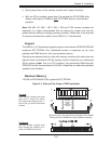
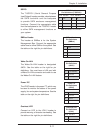
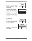
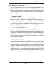
I-Button
The I-Button, located near the floppy
connector, is a computer chip enclosed in a
durable stainless container to enable RAID
5 under Software RAID mode. See the table
on the right for pin defi nitions.
I-Button
Pin Defi nitions
Pin# Defi nition
1 Ground
2 GPIO1
3 Ground