


UVS-7111 User's Manual
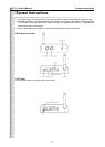
Audio/Video Output
Plug the audio/video source of your camera into the Audio/Video input, and connect your monitor or
recording equipment to the Audio/Video output.
(Note: Most cameras use a BNC connector, if your camera does not use BNC, please consult your
dealer or retailer to purchase.)
LAN Socket
Connect the LAN cable into the LAN socket.
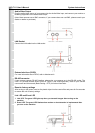
External alert bus (DI/DO)
For more information about DI/DO, refer to Attachment A.
RS-485 connector
If your camera supports RS-485 interface, please wire your cameras up to the RS-485 socket. The
UVS-7111 provides several drivers (Pelco-D, Pelco-P, and A-linking drivers). Refer to your camera
user manual and this manual (Basic Setting > PTZ) for further information.
Reset to factory settings
After turning on the power, insert a slim plastic object into the reset orice and press for ve seconds
to restore the unit to factory settings.
Link LED and Event LED
1. Link LED: The green LED lights up when you transmit images after turning on the
machine.
2. Event LED: The green LED ashes when motion or alert detection is implemented after
you turn on the machine.
7
System Instructions