


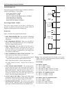
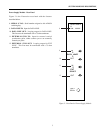
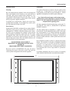

When a video loss is detected, a video loss message is
transmitted from the 2010DBVL via the RJ45 connector RS-
232 pins. An alarm contact is also provided by pins 1 and 2 of
this connector. The connector pin definitions are as follows.
RJ45 Connector Pin Definitions
Pin Function (RS-232 Code)
1 Alarm Contact Output
2 Alarm Ground
4 Receive Data (RCD)
5 Transmit Data (XMIT)
7 Ground (GND)
The RS-232 pins are connected to an RS-232 port, on the
AD1024 CPU, which is set for VIDEO LOSS use. The RS-
232 port can be connected using the supplied modularcable. if
the distance between the 2010DBVL and the CPU is less than
7 feet.
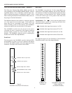
If the distance exceeds 7 feet, or if the Alarm Contact output is
used, an 8-pin Terminal Box is provided for
connections. The Terminal Box is connected to the
2010DBVL RS-232 port with the supplied modular cable. The
maximum cable length between an RS-232 device and the
Terminal Box is 1000 feet, using 18-AWG shielded, computer
grade cable.
All American Dynamics equipment is configured as RS-232
DTE (Data Terminal Equipment) devices. For DTE-to-DTE
connection to the 2010DBVL Terminal Box:
- the XMIT pin of the 1996 port is connected to RCD (pin
4) of the 2010DBVL Terminal Box.
- the RCD pin of the 1996 port is connected to XMIT (pin
5) of the 2010DBVL Terminal Box.
- the Ground of the 1996 port is connected to GND (pin 7)
of the 2010DBVL Terminal Box.
Pins 1 and 2 provide a logic-level alarm closure, in accordance
with the Alarm Contact mode set for the module (see page 13).
These pins are connected to the alarm contact inputs of a 2096
Alarm Interface Unit, pin 1 to “A” input and pin 2 to ground.
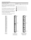
Where multiple 2010DBVL modules are used, 1981 or 2081
port expanders are used to connect these modules to the
AD1024 CPU. The 2010DBVL-1x module must be connected
to port A of the 1981, 2010DBVL-2x to port B, 2010DBVL-3x
to port C, and 2010DBVL-4x to port D. Video loss detection
will not operate unless all modules are connected to the
AD1024 CPU.
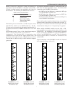
Typical connections of the 2010DBVL module are illustrated
in the Appendix, Figures A18 to A21.
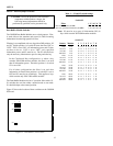
Figure 12
2010DBVL-11 to -18
Multiple-Bay System
for cameras 1-256
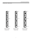
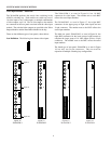
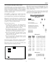
Figure 13
2010DBVL-21 to -28
Multiple-Bay System
for cameras 257-512
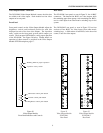
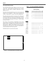
Figure 14
2010DBVL-31 to -38
Multiple-Bay System
for cameras 513-768
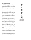
Figure 15
2010DBVL-41 to -48
Multiple-Bay System
for cameras 769-1024
SYSTEM MODULES DESCRIPTION
7
1
5
8
1
9
4
1
2
1
3
5
1
5
8
1
9
4
1
2
1
3
5
1
5
8
1
9
4
1
2
1
3
5
1
5
8
1
9
4
1
2
1
3
5