


Video Input Modules - 2016AVIM
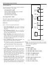
The 2016AVIM performs the actual video switching in the
AD1024 switching bay. Each module can switch any one of
16 video inputs to any video output, or multiple combinations
of video outputs, up to 16. The 16 video inputs to the module
are connected at the rear panel associated with the video input
module. The switched video outputs are provided to the Video
Output Modules and the Data Buffer Module in the bay.
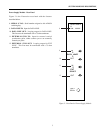
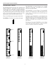
There are four different types of rear panels, shown below.
Icon Definition: The following icon denotes video inputs.
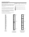
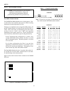
The 2016AVIM-1, as seen in Figure 16, has 16 BNC
connectors for video inputs. The number next to each BNC
reflects the actual input numbers.
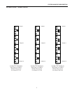
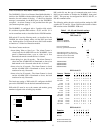
The 2016AVIM-2, as seen in Figure 17, has eight BNC
connectors for the upper group of eight video inputs and one
34-pin connector. The number next to the BNC reflects the
actual input numbers.
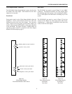
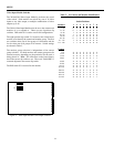
The third rear panel, 2016AVIM-3, as seen in Figure 18, has
eight BNC connectors for the lower group of eight cameras to
complete the larger group of 16 video inputs and two 34-pin
connectors. The number next to the BNC reflect the actual
input numbers.
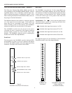
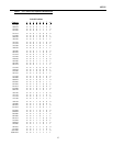
The fourth type of rear panel, 2016AVIM-4, as seen in Figure
19, has only two 34-pin connectors. They are used for
expansion in multiple switching bay configurations.
Figure 16
2016AVIM-1
Figure 17
2016AVIM-2
1
6
Input 16
Input 8
8
1
Input 1
9
4
1
2
1
3
5
8
1
O
U
T
SYSTEM MODULES DESCRIPTION
8
16
9
O
U
T
I
N
Figure 18
2016AVIM-3
Figure 19
2016AVIM-4
16
1
O
U
T
I
N