


Power Supply Set Up - Vertical Phase Adjustment
The matrix switching bays are designed as vertical interval
switches, thus giving the matrix switching bay the ability to
switch between properly phased video inputs without
producing a vertical roll, or a black bar, between each video
switch. Use of this feature allows vertical interval switching to
be controlled by the AC Line (Line Locked ), External Vertical
Drive (Generator Locked), or Composite video input.
1. AC LINE: The most common form of synchronization is
AC line lock of the vertical switching point. To use this
feature, switch the Sync Reference Selection switch to AC
LINE (see Figure 1 on page 2). This will use the AC (either 60
or 50 Hz) line to determine the vertical timing. If all video
inputs use the same phase of AC power to determine the
vertical timing, no roll will appear.
As an aid to the installer, a switch on the Power Supply
Module is available to check the vertical switch location for
each video input. This function is initiated when the SET
UP/NORMAL switch is selected to the SET UP position.
A. Connect a monitor to the top most BNC of the 2010DB-00
labeled Test/Expansion Only, or the first monitor output of
any level VOM. If the monitor card is present, connect to
the video output module monitor 1. If not, use the Data
Buffer output #1.
B. From an external keyboard call input 1 to output 1.
C. Place the SET UP/NORMAL switch to the SET UP
position. This implements the phase adjustment procedure.
Note: The Sync Test On/Off LED will be blinking when
the sync test switch is in the SETUP position.
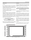
Notice that the alignment bar, displayed on output 1, shows the
location of the vertical switch with respect to the picture.
D. The phase adjustment potentiometer, accessed thru the hole
in the front panel of the Power Supply, adjusts the phase of
the vertical interval synchronization pulse for the switcher
with respect to the selected reference.
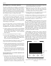
E. Adjust the position of the bar with a TV alignment tool, or
equivalent, by turning the phase potentiometer, until the
line is located as seen in Figure 30. The line should be
visible on the screen.
Once the alignment bar is set, no further adjustment to the
potentiometer is necessary.
F. Select the second video input in the system. If the
horizontal bar is not in the same location as seen in Figure
30, adjust the sync location on the "video device" (i.e.,
video camera) until the horizontal bar is located towards
the bottom of the screen. If this is not possible, and the
alignment bar is located in a different position than it was
in the previous camera, you will experience camera roll
during switching operations to that camera.
G. Repeat this for all video inputs to the system.
Note: Before adjusting all of the video inputs, quickly scan
all inputs to see if only a few are out of phase and adjust
accordingly (input one may be the only oddball!).
H. Once all cameras have been synchronized, place the SET
UP/NORMAL switch to the NORMAL position.
If multiple matrix switching bays are used, repeat steps A - H
for each bay. The sync/test output for these bays is the top
most output BNC located on each 2010DB-XX rear panel at
the first monitor of the bay, i.e., monitor 17-32, etc.
2. EXT V-DRIVE: If an external generator is used to control
the vertical switching point, switch the Sync Reference
Selection switch to EXT V-DRIVE (external vertical drive).
For proper operation, the output voltage of the generator
should not exceed 5V peak-to-peak (p-p). Connect the drive
output from the generator to the EXT SYNC IN BNC located
on the 2010PS rear panel. Connect a 75-ohm terminator to the
EXT SYNC OUT BNC. If other bays are used, loop the EXT
SYNC from input to output for all bays and terminate the last
bay EXT SYNC OUT BNC in 75-ohms.
3. EXT CAM: If composite video is used to control the
vertical switching point, switch the Sync Reference Selection
switch to EXT CAM (external camera). For proper operation,
the composite sync signal is specified at 1.1V p-p. Connect
the composite sync to the EXT SYNC IN BNC located on the
2010PS rear panel. Connect a 75-ohm terminator to the EXT
SYNC OUT BNC. If other bays are used, loop the EXT
SYNC from input to output for all bays and terminate the last
bay EXT SYNC OUT BNC in 75-ohms.
18
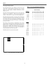
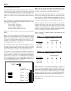
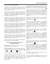
Figure 30 - Placement of Setup Alignment Bar
Alignment bar should be visible on the monitor and not in the
vertical sync.
alignment bar
Monitor 1
SETUP