


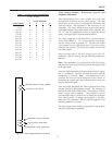


LEVEL 1 - 1024 X 16, Five Bay System
A five bay, Level 1 system allows a maximum of 1024 video
inputs switched to a maximum 16 video outputs. Bays one
through four each consists of 256 video inputs, and bay five
consists of the 16 video outputs.
From the rear of bay one, the modules are installed at the
factory in the following manner; the far right module is the
2010PS, the next module is the 2010DB-11 with 16 BNCs for
connection to the 2024VOM-2 modules, followed by sixteen
2016AVIM-1 modules, inputs 1 - 256.
From the rear of bay two, the modules are installed at the
factory in the following manner; the far right module is the
2010PS, the next module is the 2010DB-21 with 16 BNCs for
connection to the 2024VOM-2 modules in bay five, followed
by sixteen 2016AVIM-1 modules, inputs 257 - 512.
From the rear of bay three, the modules are installed at the
factory in the following manner; the far right module is the
2010PS, the next module is the 2010DB-31 with 16 BNCs for
connection to the 2024VOM-2 modules in bay five, followed
by sixteen 2016AVIM-1 modules, inputs 513 - 768.
From the rear of bay four, the modules are installed at the
factory in the following manner; the far right module is the
2010PS, the next module is the 2010DB-41 with 16 BNCs for
connection to the 2024VOM-2 modules in bay five, followed
by sixteen 2016AVIM-1 modules, inputs 769 - 1024.
From the rear of bay five, the modules are installed at the
factory in the following manner; the far right module is the
2010PS, the next module is the 2010DB-00, followed by four
2024VOM-2 modules for outputs 1 - 16.
Smaller matrices such as those ordered with future expansion
in mind, may have fewer modules installed.
IDENTIFY THESE MODULES CAREFULLY
BEFORE PROCEEDING.
Data Interconnect: See LEVEL 1 - 448 X 16, two bay system
and connect all bays in a similar manner.
Video Interconnections: The 16 video outputs from bay 1,
through 4 are located on the rear panel of the 2010DB-11 ,
-21 , -31 , and -41 respectively.
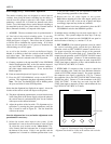
They are grouped by fours and identified by their icons.
Each 2024VOM-2 is similarly grouped with four sections of
four BNCs, with identifying icons. A fifth section of four
BNCs, in the lower left corner, is used for video outputs. The
left most 2024VOM-2 module is assigned to outputs 1 - 4, the
next for outputs 5 - 8, etc. See Figure 22, Video Output
Module, page 9.
Using high grade RG-59U video cables, connect the top most
BNC from bay 1 on the 2010DB-11 panel, numbered 1, to the
2024VOM-2 in bay 5, for output 1, matching icon to icon.
Continue in this manner until connections 1 - 4 of the 2010DB-
11 panel are connected to inputs 1 - 4 of the first 2024VOM-2.
Proceed to the next group of four BNCs on the 2010DB-11 and
connect these to the second 2024VOM-2 for outputs 5-8.
Continue in this manner until all 16 connections of the
2010DB-11 panel are connected to the 2024VOM-2s for
outputs 1 - 16.
Connect the top most BNC from bay 2 on the 2010DB-21
panel, numbered 1, to the 2024VOM-2 in bay 5, for output 1,
matching icon to icon.
Continue in this manner until connections 1 - 4 of the2010DB-
21 panel are connected to inputs 1 - 4 of the 2024VOM-2.
Proceed to the next group of four BNCs on the 2010DB-21 and
connect these to the second 2024VOM-2 for outputs 5-8.
Continue in this manner until all 16 connections of the
2010DB-21 panel are connected to the 2024VOM-2s for
outputs 1 - 16.
Connect the top most BNC from bay 3 on the 2010DB-31
panel, numbered 1, to the 2024VOM-2 in bay 5, for output 1,
matching icon to icon.
Continue in this manner until connections 1 - 4 of the 2010DB-
31 panel are connected to inputs 1 - 4 of the 2024VOM-2.
Proceed to the next group of four BNCs on the 2010DB-31 and
connect these to the second 2024VOM-2 for outputs 5-8.
Continue in this manner until all 16 connections of the
2010DB-31 panel are connected to the 2024VOM-2s for
outputs 1 - 16.
Connect the top most BNC from bay 4 on the 2010DB-41
panel, numbered 1, to the 2024VOM-2 in bay 5, for output 1,
matching icon to icon.
Continue in this manner until connections 1 - 4 of the2010DB-
41 panel are connected to inputs 1 - 4 of the 2024VOM-2.
Proceed to the next group of four BNCs on the 2010DB-41 and
connect these to the second 2024VOM-2 for outputs 5-8.
Continue in this manner until all 16 connections of the
2010DB-41 panel are connected to the 2024VOM-2s for
outputs 1-16.
See Appendix Figure A18, Video Interconnections, for
illustration of these interconnections.
If there are less than four 2024VOM-2 modules in the system
the remaining BNCs on the 2010DB-XX do not require any
connection.
SYSTEM CONFIGURATIONS
25