


SYSTEM MODULES
The following pages describe the plug-in modules available for
AD1024 switching bays. These include:
Power Supply Module, 2010PS
Data Buffer Module, 2010DB
Video Loss Detection Data Buffer Module, 2010DBVL
Video Input Module, 2016AVIM
Video Output Module, 2024VOM
Master Date Time Module, 2024MDT
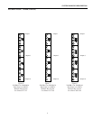
Power Supply Module - 2010PS
The power supply module for the matrix switching bay
converts AC power to the necessary DC voltages which are
supplied to all the modules in the switching bay.
Front Panel
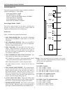
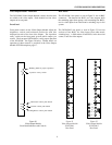
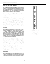
Figure 1 illustrates the features described below.
1- SYNC TEST ON/OFF LED: This red LED is illuminated
when the SET UP/NORMAL switch (below) is in the SET
UP position.
2- SET UP/NORMAL SWITCH: When set to the SET UP
position, this switch implements sync test and adjustment.
(See Power Supply Setup, page 18.)
3- SYNC LOSS LED: This red LED is off if video sync is
locked. When illuminated, it indicates that sync is not
locked due either to a poor sync signal, no sync signal, or
the wrong sync signal (as determined by the setting of the
sync selection switch below).
4- SYNC REFERENCE SELECTION SWITCH: This
switch selects one of three video sync references:
EXT V-DRIVE (Up position): Selects the external vertical
drive pulse input on the rear panel (EXT SYNC IN).
EXT CAM (Center position): Selects composite video.
AC LINE (Down position): Selects the AC line (as
supplied).
5- SYNC PHASE ADJUSTMENT: This potentiometer,
accessed thru the hole in the front panel of the Power
Supply, adjusts the phase of the sync pulse with respect to
the selected reference. When the sync test switch is set to
SET UP, a horizontal trace line is displayed on Monitor 1,
showing the location of the sync pulse with respect to the
picture. (See Power Supply Setup, page 18.)
6- +9 VDC AND -9 VDC LED's: These green LED's, when
illuminated, indicate the presence of DC voltages (Note: For
the 230 VAC systems, the output voltages are +/-8 VDC).
7- POWER ON/OFF SWITCH: This switch is used to apply
power to the bay. When the switch is in the ON position, a
green light is illuminated behind the Power On/Off Switch.
Fusing: Four replaceable fuses are located on the power
supply circuit board. Replacement fuses must meet national
and local use code requirements.
Fuse Ratings:
For 120VAC Systems:
F1: 125V, 5 AMP, 5 x 20 mm
F2: 125V, 5 AMP, 5 x 20 mm
F3: 250V, SB, 0.5 AMP, 5 x 20 mm, UL listed
F4: 250V, SB, 0.5 AMP, 5 x 20 mm, UL listed
For 230VAC CE Compliant Systems:
F1: 250V, T, 3.15 AMP, 5 x 20 mm
F2: 250V, T, 3.15 AMP, 5 x 20 mm
For 230VAC Non-CE Compliant Systems:
F1: 125V, 5 AMP, 5 x 20 mm
F2: 125V, 5 AMP, 5 x 20 mm
F3: 250V, T, 0.25 AMP, 5 x20 mm
F4: 250V, T, 0.25 AMP, 5 x 20 mm
SYSTEM MODULES DESCRIPTION
Figure 1 - Front Panel of Power Supply Module
SET UP
NORMAL
EXT V-DRIVE
EXT CAM
AC LINE
PHASE
+9VDC
-9VDC
SYNC
LOSS
1
2
3
4
5
6
7
2