


SYSTEM CONFIGURATIONS
LEVEL 3 SYSTEMS
Level 3 systems use up to fourteen 2010 matrix switching bays
each with the 2010PS Power Supply Module and 2010DB-XX
Data Buffer module. Level 3 systems can consist of up to 192,
448, 704, 768, 960, or 1024 video inputs and up to 48 video
outputs, arranged as 2, 3, 4, 6, 7, 9, 10, 12, and 14 bay systems.
For a Level 3 system with Video Loss Detection capability, the
video output for monitor 48 is replaced by the Video Loss
Detection function in the 2010DBVL Module. Since each
2010DBVL can detect video losses for a maximum of 256
cameras, an additional 2010DBVL Module is required for each
block of 256 cameras. The camera bays that contain video
outputs for monitors 32 through 47 would use a 2010DBVL-
13, a 2010DBVL-23, a 2010DBVL-33 and a 2010DBVL-43
for each respective group of 256 cameras. In a multi-bay
system where the last bay contains both camera modules and
monitor modules, that bay would use a 2010DBVL-00 module.
In a fourteen-bay system, the last two bays are monitor bays
and would use the 2010DB-00 Module, not the 2010DBVL.
LEVEL 3 - 192 X 48, Three Bay System
A three bay, Level 3 Systems allows a maximum of 192 video
inputs switched to a maximum 48 video outputs. Bay one
consists of 192 video inputs switched to video outputs 1-16,
bay two consists of 192 video inputs switched to video outputs
17-32 and bay 3 consists of 192 video inputs switched to video
outputs 33-48.
From the rear of bay one, the modules are installed at the
factory in the following manner; the far right module is the
2010PS, the next module is the 2010DB-00, followed by
twelve 2016AVIM-2 modules and four 2024VOM-1 modules,
inputs 1-192, outputs 1-16.
From the rear of bay two, the modules are installed at the
factory in the following manner; the far right module is the
2010PS, the next module is the 2010DB-00, followed by
twelve 2016AVIM-3 modules and four 2024VOM-1 modules,
inputs 1-192, outputs 17-32.
From the rear of bay three, the modules are installed at the
factory in the following manner; the far right module is the
2010PS, the next module is the 2010DB-00, followed by
twelve 2016AVIM-4 modules and four 2024VOM-1 modules,
inputs 1-192, outputs 33-48.
IDENTIFY THESE MODULES CAREFULLY
BEFORE PROCEEDING.
Data Interconnect: Connect a 75-ohm coaxial cable from the
DATALINE-1 output on the AD1024 CPU, to the DATA IN
BNC of bay 1. Connect a 75-ohm coaxial cable from the
DATA OUT BNC of bay 1 to the DATA IN BNC on the
2010PS rear panel in bay 2. Connect a 75-ohm coaxial cable
from the DATA OUT BNC of bay 2 to the DATA IN BNC
2010PS rear panel in bay 3. Connect a 75 ohm BNC terminator
(supplied with the CPU) to the Data OUT BNC of bay 3.
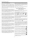
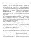
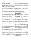
Video Input Connections: The 2016AVIM-2 is identified
with the camera input icon.
The starting camera number for the particular VIM is located
at the top BNC. Each 2016AVIM-2 includes 8 BNCs for video
input connections, a coaxial ribbon connector, labeled OUT,
for video interconnection, and one 16 conductor coaxial ribbon
cable. See Figure 17, Video Input Module, page 8.
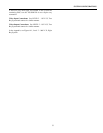
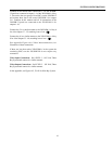
The 2016AVIM-3 is identified with the camera input icon. The
starting camera number for the particular VIM is located at the
top BNC. Each 2016AVIM-3 includes 8 BNCs for video input
connections, two coaxial ribbon connectors, labeled IN and
OUT and one 75 ohm terminator. See Figure 18, page 9.
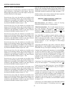
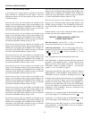
The 2016AVIM-4 is identified with the camera input icon. The
starting camera number for the particular VIM is located at the
top of rear panel. Each 2016AVIM-4 includes two coaxial
ribbon connectors, labeled IN and OUT, for video
interconnection, and one 16 conductor coaxial ribbon cable.
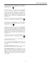
Connect one end of the supplied coaxial ribbon cable to the
coaxial ribbon connector labeled "OUT" of the 2016AVIM-2.
NOTE: Tighten the two connector screws alternately to
keep the connectors aligned. Tightening on one side only
may damage the connector. Alternate between each side.
Connect the other end of the coaxial ribbon cable to the coaxial
ribbon connector labeled "IN" of the 2016AVIM-3 following
the alternating turn method noted above. Connect one end of
the second coaxial ribbon cable supplied with the 2016AVIM-4
to the coaxial ribbon connector labeled OUT of the
2016AVIM-3. Connect the other end of the ribbon cable to the
coaxial ribbon connector labeled IN of the 2016AVIM-4
following the alternating turn method above. Place a 75 ohm
terminator (P/N2016 TERM) in the coaxial ribbon connector
labeled OUT of the 2016AVIM-4. Continue in this manner for
each 2016AVIM pair. A pair meaning the upper and lower
halves of multiples of 16; for example, 1 to 8 and 9 to 16 being
a pair, 17 to 24 and 25 to 32 also being a pair.
In succession, connect the video inputs to the 2016AVIM-2
and 2016AVIM -3 module pairs. Connect eight video inputs to
2016AVIM-2 and the next eight video inputs to 2016AVIM-3.
Continue in this fashion until all video inputs are connected.
36