


Master Date Time Module - 2024MDT
The 2024MDT Master Date Time Module provides looping
connection of the video input signals and insertion of system
time and date information on the video output connections.
These modules are used with dedicated inputs for dedicated
outputs, and do not perform any inter-bay switching.
The 2024MDT has four looping video inputs and four separate
video outputs with system time and date information.
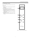
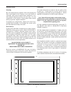
Front Panel
The 2024MDT front panel controls the brightness, vertical, and
horizontal position for each title displayed on each of the four
video outputs. The 4-position rotary switch governs which
output is selected for control. The LED blinks to verify proper
operation of the 2024MDT. The front panel controls operate
identical to those on the 2024VOM module, see Figure 20 on
page 9. Further details on operation of these controls is
provided in the Video Output Module SETUP description,
page 17.
Rear Panels
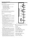
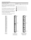
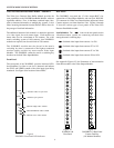
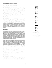
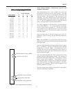
The 2024MDT rear panel, shown in Figure 23, has 12 BNC
connectors and handles four separate video input channels: A,
B, C, and D. The bottom four BNC's are video outputs which
contain time and date information from the system Data Line
interface. The upper four groups of BNC's are for video inputs
from matrix switching bays and looping outputs to other video
equipment, such as VCR's. Each BNC pair in the upper groups
is an unterminated looping connection.
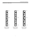
Video inputs to the 20204MDT module may be connected to
either of the input pair of BNC's for each input channel. If the
video is terminated in the 2024 module, and not looped to
additional equipment via the paired BNC, a 75-ohm
terminating cap must be connected to the paired input BNC.
75-ohm terminating caps are supplied for the looping BNC
connectors.
If any video input is looped to another video device, ensure
that the line is terminated properly in 75 ohms.
The video output connections from the bottom four BNC's on
each 2024 module must be terminated in 75 ohms.
Setup Switches
The 2024MDT module PCB card contains jumpers that are set
to identify the monitors that the video output is being directed
to. These are factory set for monitors one, two, three, and four.
10
SYSTEM MODULES DESCRIPTION
A
A
B
B
C
C
D
D
A
B
C
D
Figure 23
2024MDT Rear Panel
4 channels, looping inputs
4 channels, outputs