


LEVEL 1 - 256 X 15, One Bay System with Video Loss
Detection
A one bay, Level 1 system, with video loss detection and
without video titles, allows a maximum of 256 video inputs
switched to a maximum of 15 video outputs.
This system is the same configuration of modules as the
LEVEL 1 - 256 X 16 system except that the 2010DBVL-01
Video Loss Detection Data Buffer module is installed in place
of the 2010DB-01 module. The connections are as described
for that system configuration, except that only 15 BNCs are
provided for video outputs.
See Appendix Figure A18, 256 X 15, One Bay System with
Video Loss Detection Module.
LEVEL 1 - 192 X 16, One Bay System
A one bay, Level 1 system, with 2024VOM modules for video
titles, allows a maximum of 192 video inputs switched to a
maximum of 16 video outputs.
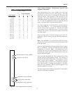
From the rear of the bay, the modules are installed at the
factory in the following manner; the far right module is the
2010PS; the next module is the 2010DB-00, followed by
twelve 2016AVIM-1 modules, and four 2024VOM-1 modules.
Smaller matrices, such as those ordered with future expansion
in mind, may have fewer modules installed.
IDENTIFY THESE MODULES CAREFULLY
BEFORE PROCEEDING.
Data Interconnect: Connect a 75-ohm coaxial cable from the
DATALINE-1 output on the AD1024 CPU to the DATA IN
BNC on the 2010PS rear panel. Connect a 75-ohm BNC
terminator (supplied with the CPU) to the Data Out BNC on
the Power Supply rear panel.
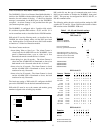
Video Input Connections: The 2016AVIM is identified with
the video input icon.
The starting video input number, for the particular VIM, is
located at the top BNC. Each 2016AVIM-1 includes 16
terminated BNCs for video input connections. The first
2016AVIM-1, located immediately to the left of the 2010DB-
00, is for video inputs 1-16, the second 2016AVIM-1 module is
for inputs 17- 32, etc.
In succession, connect the video inputs to each 2016AVIM-1
module, top to bottom. Each VIM will accept 16 video inputs.
Continue until all inputs are connected to the system. Unused
video inputs, on the VIM, do not require any external
connection or termination, and may be left open. See Figure
16, Video Input Module, page 8.
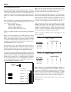
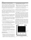
Video Output Connections: Each 2024VOM-1 has a rear
panel with 16 BNCs. For single bay systems, only the bottom
four BNCs are used for video output connections. The left
most module is assigned to outputs 1 - 4. Moving left to right,
the next VOM module is assigned to outputs 5 - 8, etc. (The
modules are numbered 1 - 4, 5 - 8, etc.) Connect the video
outputs to any device that accepts standard video such as
monitors or video recorders. See Figure 21, Video Output
Module, page 9.
In the Appendix, see Figure A2, 192 X 16, One Bay System.
SYSTEM CONFIGURATIONS
21