


48
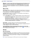
AXIS 213 - Connection Module
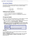
Connection Module
The connection module connects to the camera and is configured and controlled via
the camera’s user interface. The Connection module is an optional accessory
providing the following:
• audio in / out
• 3 relay outputs
• 2 digital inputs
• video in / out
• RS-232C Serial port
Installing the audio equipment
1. Connect a microphone (not supplied) to the Audio IN socket.
2. Connect a loudspeaker (not supplied) to the Audio OUT socket (amplified
speakers only).
I/O inputs and outputs
The I/O inputs / outputs are used in applications for, e.g. event triggering, time lapse
recording, alarm notification via email, picture storage to FTP locations.
• Input - e.g. a doorbell. If the doorbell is pressed, the state changes, and the input
will be active (shown under Event Configuration > Port Status).
• Output - e.g. an alarm device that can be activated from Output buttons on the
Live View page, or as an action for an Event Type. The output will show as active
(under Event Configuration > Port Status) if the alarm device is activated.
Video Out
Via a standard BNC connector, this output allows the AXIS 213 to be connected
directly to traditional CCTV systems.
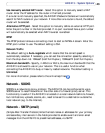
Video In and RS-232C can be configured under Plain config for use in advanced
applications (see System Options > Advanced > Plain Config). Intended for
advanced users only.
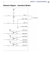
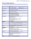
I/O Description
Alarm In 1,2 Connect to GND to activate or leave floating (unconnected) to deactivate
Alarm GND
Alarm Out
1A,1B;2A,2B;3A,3B
Active output, electrical connection between A and B. Non active output, no
connection between A and B. Imax=100mA, VMax=24V