


E-14
CONTROLS,
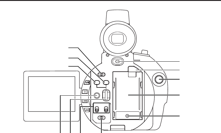
INDICATORS AND CONNECTORS
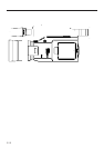
Rear Section
POWER
OFF
ON
MODE
PUSH
CAM-B
VTR
SHUTTER
MENU
AUDIO
MONITOR
MIC1
MIC2
CH-2CH-1
CH-2
MIX
CH-1
GAIN
CAM-A
BAR
AW
FWD
REV
!3
!5
!4
!6
!7
@0
!9
!8
@4@3@2@1
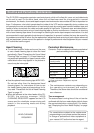
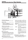
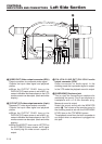
C [POWER] POWER switch
Turn the power ON and OFF with this switch.
D Battery holder
Mount the optional battery pack BN-V416 or BN-
V428 here. (
☞
See page 34.)
The BN-V416 battery pack cannot be used when
the optional Network Pack KA-DV300 is used.
E Battery lock release button
Press this button to remove the battery pack.
F [DC INPUT] DC connector
Power input connector for 7 V DC. Accepts the
optional AC adapter AA-P30. The power range
is 6 V to 12 V.
G REC Start/Stop button
This button starts and stops recording. When
the GY-DV300 is in the shooting mode, pressing
this button starts the recording. Pressing the
button during a recording engages the
recording-pause (standby) mode.
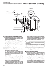
H [MODE] Mode selector switch
Set in accordance with the operating mode of
the GY-DV300. When used in the shooting mode,
the switch is set to “CAM-A” or “CAM-B”. When
used in the VTR playback mode, it is set to
“VTR”. When set to “CAM-A” or “CAM-B” in the
shooting mode, two separate sets of setting
values for recording can be set by means of the
menu screens.
“CAM-A” : In this position, shooting takes
place in accordance with the
conditions set for “CAM-A” on the
menu screen.
“CAM-B” : In this position, shooting takes
place in accordance with the
conditions set for “CAM-B” on the
menu screen.
“VTR” : Set to this position when performing
VTR playback.
Also set to this position to record
the video signal output from the DV
connector with another video
component equipped with DVI/O
connector.
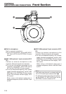
I [GAIN] Sensitivity selector button
This button is for manual adjustment of
sensitivity. It works when the AE item is set to
OFF on the OPERATION menu screen.