


E-49
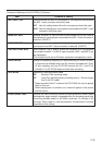
Setting
MIC 1
MIC 2
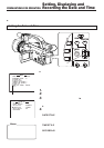
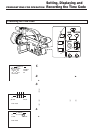
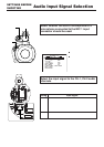
Audio Input Signal Selection
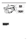
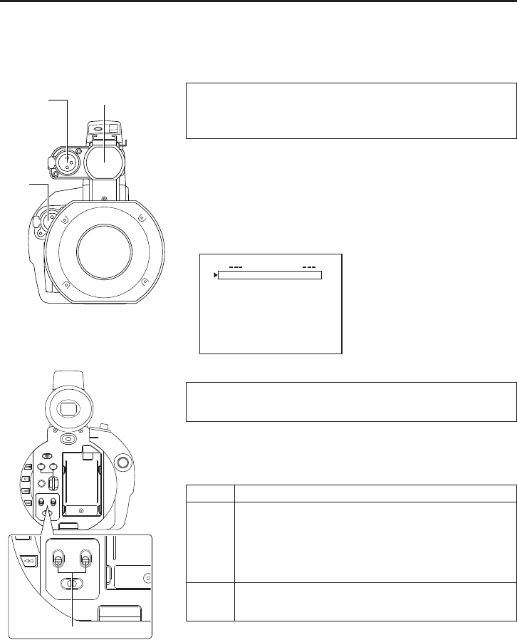
The GY-DV300 is provided with three sources for audio input (i.e., built-in microphone and input connectors
MIC 1 and MIC 2 for external microphones).
Two channels of sound can be recorded on the tape in digital PCM format. Select for each channel (CH1
and CH2) which sound should be recorded on the channel. The sound of each of the input sources is
monaural.
Select whether the built-in microphone or a
microphone connected to the MIC 1 input
connector should be used.
Built-in microphone
MIC 1
input
connector
MIC 2
input
con-
nector
POWER
OFF
ON
MODE
PUSH
CAM-B
VTR
SHUTTER
MENU
AUDIO
MONITOR
MIC1
MIC2
CH-2CH-1
CH-2
MIX
CH-1
GAIN
CAM-A
BAR
AW
FWD
REV
AUDIO
MIC1
MIC2
CH-2CH-1
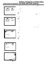
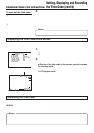
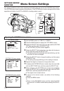
The built-in microphone and a microphone connected to the MIC 1
input connector cannot be used at the same time.
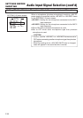
When using the GY-DV300 with the built-in microphone or a
microphone connected to the MIC 1 input connector, select which
one to use by setting the MIC1 INPUT SEL item on the SYSTEM
[1/2] menu screen.
SYSTEM [1/2] menu screen
MIC1 INPUT SEL
STSY EM 1 / 2
][
IT
N
WIND C
U
TMIC1
WIND C
U
TMIC2
O
FF
O
FF
O
FF
+
48V MI
C1
O
FF
+
48V MI
C2
AUDIO
MOD
E
4
8K
REC MO
D
E
S
P
LONG P
A
USE T IME
30
MIN
NEXT P
A
GE
PAGE B
A
CK
Ⅲ Set to INT to use the built-in
microphone.
Ⅲ Set to MIC 1 to use the micro-
phone connected to the XLR
input connector.
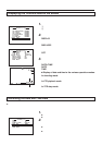
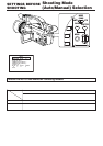
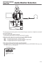
Select the input signal to the CH-1, CH-2 audio
channels
The audio signal input to the CH-1, CH-2 audio channels is selected
with the AUDIO input selector switch.
The input can be set separately for each channel.
The same sound can be input to both the CH-1 and CH-2 channels.
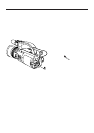
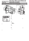
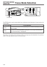
AUDIO input signal selector switch
Input Signal
The microphone sound from the built-in microphone
or a microphone connected to the MIC 1 input
connector.
(Make the selection with the MIC1 INPUT SEL item on
the SYSTEM [1/2] menu screen.)
The microphone sound from a microphone connected
to the MIC 2 input connector.
SETTINGS BEFORE
SHOOTING