


11
Ⅲ Connections
Ⅲ Settings
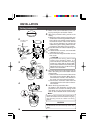
When connecting
●Turn OFF the power supply to all equipment to be used before making connections.
●Carefully read the Instruction Manual for each piece of equipment to be used before
making connections.
●For the appropriate connection cables and the length of these, carefully read “Connections
to Camera Terminal Board” on page 12.
●The control signal cable cannot be used for loop connection.
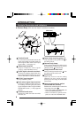
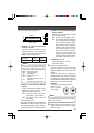
Lug plates
AC 24 V power cable
To AC 24V power
supply
To RM-P2580
To VIDEO INPUT
terminal on
RM-P2580
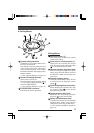
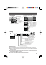
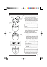
Connecting the control signal cable
(
Use a twisted-pair cable for connection. ੬ See page 13.
)
Camera 2
terminal board
Connect:
Camera TX+ to RM-P2580 RX+
Camera TX– to RM-P2580 RX–
Camera RX+ to RM-P2580 TX+
Camera RX– to RM-P2580 TX–
The A B C D marks indicated
on both the camera terminals
and the RM-P2580 terminals
facilitate correct connections.
Connect the terminals with
identical marks.
C TX+
D TX–
A RX+
B RX–
TX+ A
TX
– B
RX
+ C
RX– D
TX
+ A
TX
– B
RX
+ C
RX– D
TX
+ A
TX
– B
RX
+ C
RX– D
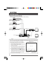
RM-P2580
Camera 1
terminal board
Camera 3
terminal board
Control
signal cable
Video signal cable
(coaxial cable)
Terminal board
RX+ C
RX– D
A TX+
B TX–
1234
ON
0
9
8
7
6
5
4
3
2
1
0
9
8
7
6
5
4
3
2
1
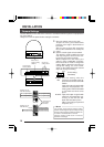
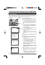
Camera ID setting switches
Set to match the RM-P2580 VIDEO
INPUT terminal number for each
camera.
Switch 3: Set this to ON (signal termination ON) only
on the camera placed at the end of the
control signal cable.
Set to OFF on all other cameras.
Switch 2: Set to OFF (DUPLEX) side.
Switch 1: Set to ON (MULTIDROP) side.
Control signal selector switch:
Set to the RS-422A/RS-485 side.
(Example: Camera 1
ID “×10” position 0,
ID “×1” position 1)
Switch 4: Select the synchronization method of the
camera image.
Set the switch on all cameras to ON (Line
Lock) and match with the V. PHASE.
(Only possible in 60 Hz regions.)
(੬ See page 20.)