


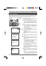

15
Double
figures
Single
figures
0
9
8
7
6
5
4
3
2
1
0
9
8
7
6
5
4
3
2
1
"1""0"
● Switch 4: Synchronization signal
selector switch
Switches the synchronization method
of the camera image.
OFF: Internal synchronization (INT)
ON:
The camera’s vertical synchroniza-
tion is matched with the frequency
of the AC 24V line power supply.
When switching between mul-
tiple cameras using a switcher,
selecting this mode and adjust-
ing the vertical phase can re-
duce the monitor sync distur-
bances occurring when the
camera image is switched. (This
cannot be used in regions where
the power frequency is 50 Hz.)
● Switches 5, 6, 7, 8
These switches are not used.
(Set them to OFF.)
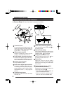
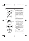
4.
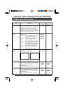
Camera ID setting switches
Camera ID setting is only performed
when the system connection selector
switches (Switch 1 and 2) are set to “RM-
P2580”.
The camera ID number is a number to
identify each of the cameras connect to
the RM-P2580. The camera ID number
should be the same as the number of
the RM-P2580 VIDEO INPUT terminal
to which the camera is connected.
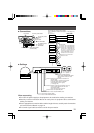
Example:
The camera connected to VIDEO
INPUT 1 is set
to “01” as shown
on the right.
Memo:
If the camera ID numbers of cameras connect
to the RM-P2580 are duplicated, the system
will not work correctly.
5.
When setting of the switches is com-
pleted, close the cover over the setting
switches again.
Memo:
Switch 1 and 2 are used to specify the
form of the control signal cable connection
between the remote control unit and the
camera and the communication protocol.
Switch 1 (Initial setting: OFF)
OFF: POINT TO POINT
ON: MULTIDROP
Switch 2: (Initial setting: OFF)
OFF: DUPLEX
(two-way data transmission)
ON: SIMPLEX
(one-way data transmission)
● Switch 3: Termination ON/OFF
switch
This is a termination ON/OFF switch
between the “RX+” and “RX–” control
signal connection terminals.
ON: The “RX+” to “RX–” route is ter-
minated by a 110Ω resistor.
OFF: The RX+ to RX– route is not
terminated.
(Initial setting: OFF)
In a system using the Remote Control Unit
RM-P2580, set this to “ON” only on the
camera placed at the end of the control sig-
nal cable. Set to OFF on all other cameras.
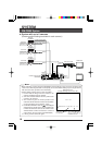
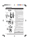
3.
Set system setting switches.
Set the system connection selector
switches (Switch 1, 2) in accordance
with the equipment that the camera
body is to be connected to.
Connecting
equipment
Switch 1 Switch 2
RM-P2580 ON OFF
● Switch 1, 2: System connection
selector switch
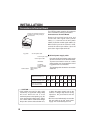
12345678
1
ON
1
OFF
Switches
ON
Switch numbers